## Neural-Logical Reasoning Diagram
### Overview
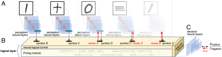
The image illustrates a neural-logical reasoning system, processing visual input through perception neural layers, integrating it with a Prolog module via a neural-logical tunnel, and making decisions based on relational features. The diagram shows how visual symbols are processed and revised using logical rules.
### Components/Axes
* **A:** Represents the input layer with handwritten symbols (1, +, 0, =, /). Each symbol is processed by perception neural layers.
* **Labels:** "perception neural layers"
* **B:** Represents the logical layer, consisting of a "neural-logical tunnel" and a "Prolog module". This layer processes the symbols and revises them based on logical rules.
* **Labels:** "symbol B", "symbol C", "revise A", "symbol D", "revise D", "revise B", "symbol C", "neural-logical tunnel", "Prolog module", "logical layer"
* **C:** Represents the decision neural layers, which output a decision based on relational features.
* **Labels:** "decision neural layers", "relational features", "Positive", "Negative", "error"
* **Arrows:** Red arrows indicate error signals or revisions. Black arrows indicate the flow of information.
### Detailed Analysis or ### Content Details
* **Input Symbols (A):**
* The diagram shows five handwritten symbols: '1', '+', '0', '=', and '/'.
* Each symbol is fed into a stack of "perception neural layers", represented as a cube.
* The output of these layers is a set of features, represented as a row of blue squares.
* **Logical Layer (B):**
* The "neural-logical tunnel" connects the perception neural layers to the "Prolog module".
* The Prolog module contains logical rules, such as:
* `eq([A,B,C]) :- dig(A), op(B), eq(C).`
* `eq([0,+,1,-,1]).`
* `abduce([A, B, A,C,A], [op(0,1,1)]).`
* `rules([op(0,1,1)]).`
* `eq([D]).`
* `eq([D,+,*,=,D]).`
* The symbols are processed and potentially revised based on these rules. For example, "revise A", "revise B", and "revise D" are explicitly labeled.
* **Decision Layer (C):**
* The "decision neural layers" receive "relational features" from the logical layer.
* Based on these features, the system makes a decision, indicated by the "Positive" and "Negative" outputs.
* An "error" signal is shown as a red arrow pointing back into the decision layer.
### Key Observations
* The diagram illustrates a hybrid system combining neural networks for perception and logical reasoning using Prolog.
* The "revise" labels indicate that the system can correct or refine its understanding of the input symbols based on logical rules.
* The error signal suggests a feedback loop for learning or adaptation.
### Interpretation
The diagram demonstrates a system that integrates visual perception with logical reasoning. The neural networks handle the initial processing of visual input, while the Prolog module applies logical rules to interpret and revise the symbols. This approach allows the system to handle noisy or ambiguous input by leveraging logical constraints. The error signal suggests that the system can learn from its mistakes and improve its performance over time. The system is designed to process and understand symbolic information, potentially for tasks such as mathematical problem-solving or logical inference.