\n
## Diagram: Two-Stage System Architecture Process Flow
### Overview
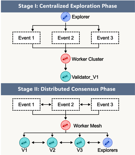
The image is a technical diagram illustrating a two-stage process flow for a distributed system. It depicts a transition from a centralized exploration phase to a distributed consensus phase, using icons and labeled components to represent different roles and their interactions. The diagram is divided horizontally into two main sections, each with a distinct title bar.
### Components/Axes
**Title Bars:**
- Top Section Title: "Stage I: Centralized Exploration Phase" (white text on a dark blue-gray background).
- Bottom Section Title: "Stage II: Distributed Consensus Phase" (white text on a dark blue-gray background).
**Icons & Labels (with approximate color descriptions):**
- **Explorer:** Represented by a blue circular icon containing a stylized ant. Appears in both stages.
- **Event 1, Event 2, Event 3:** Represented by rectangular boxes with dashed borders. Appear in both stages.
- **Worker Cluster:** Represented by a red circular icon containing a stylized ant. Appears only in Stage I.
- **Validator_V1:** Represented by a teal circular icon containing a stylized ant. Appears only in Stage I.
- **Worker Mesh:** Represented by a red circular icon containing a stylized ant. Appears only in Stage II.
- **V1, V2, V3:** Represented by teal circular icons containing a stylized ant. Appear only in Stage II.
- **Explorers (plural):** Represented by a blue circular icon containing a stylized ant. Appears only in Stage II.
**Flow Indicators:**
- Solid black arrows indicate the direction of process flow or data transmission.
- Double-headed arrows (↔) indicate bidirectional communication or interaction.
### Detailed Analysis
**Stage I: Centralized Exploration Phase**
1. **Flow:** A single "Explorer" (blue) at the top connects via downward arrows to three parallel "Events" (Event 1, Event 2, Event 3).
2. The three Events then connect via downward arrows that converge into a single "Worker Cluster" (red).
3. The Worker Cluster connects via a single downward arrow to a single "Validator_V1" (teal).
4. **Spatial Layout:** The Explorer is centered at the top. The three Events are arranged horizontally in a row below it. The Worker Cluster is centered below the Events, and the Validator_V1 is centered at the bottom of this stage.
**Stage II: Distributed Consensus Phase**
1. **Flow:** The three "Events" (Event 1, Event 2, Event 3) are arranged horizontally and connected to each other with double-headed arrows (↔), indicating peer-to-peer communication.
2. The three Events connect via downward arrows that converge into a single "Worker Mesh" (red).
3. The Worker Mesh connects via multiple downward arrows to four components arranged in a horizontal row at the bottom: "V1" (teal), "V2" (teal), "V3" (teal), and "Explorers" (blue).
4. **Bidirectional Communication:** Double-headed arrows (↔) connect V1↔V2, V2↔V3, and V3↔Explorers, indicating a mesh network of communication among the validators and explorers.
5. **Spatial Layout:** The three interconnected Events are centered at the top of this stage. The Worker Mesh is centered below them. The four bottom components (V1, V2, V3, Explorers) are evenly spaced in a horizontal row.
### Key Observations
1. **Structural Shift:** The architecture evolves from a linear, top-down hierarchy in Stage I (Explorer → Events → Cluster → Single Validator) to a networked, peer-inclusive model in Stage II (Interconnected Events → Mesh → Multiple Validators & Explorers).
2. **Role Proliferation:** A single "Validator_V1" in Stage I becomes three distinct validators (V1, V2, V3) in Stage II. The singular "Explorer" also becomes a plural "Explorers" entity in the final layer of Stage II.
3. **Communication Pattern:** Communication changes from strictly unidirectional (downward arrows) in Stage I to a mix of unidirectional (Events to Mesh) and bidirectional (between Events, and among Validators/Explorers) in Stage II.
4. **Component Renaming:** The central processing unit changes from "Worker Cluster" to "Worker Mesh," suggesting a change in internal architecture from a clustered to a mesh-based topology.
### Interpretation
This diagram illustrates a conceptual model for scaling and decentralizing a system, likely for tasks involving event processing, validation, and exploration (e.g., in distributed computing, blockchain, or multi-agent systems).
- **Stage I** represents a **centralized, exploratory bootstrapping phase**. A single explorer identifies or generates events, which are processed by a centralized cluster and validated by a single entity. This is efficient for initial setup or data gathering but creates single points of failure (the Explorer, the Cluster, the Validator).
- **Stage II** represents the **mature, decentralized operational phase**. The events themselves form a communicative network. The processing layer becomes a "Mesh," implying more resilient and distributed coordination. Most critically, validation and exploration are distributed across multiple nodes (V1, V2, V3, Explorers) that communicate directly with each other. This creates a robust consensus mechanism where no single entity is authoritative, enhancing fault tolerance and security.
The progression suggests a design philosophy where a system begins with centralized control for efficient exploration and learning, then transitions to a distributed consensus model for resilient, scalable, and trustless operation. The persistence of the "Explorer" role in both stages, and its integration into the final validator mesh, indicates that continuous discovery or data input remains a core function even in the decentralized state.