## Logic Diagram: Prime and Sub-Prime Logic Gate Network
### Overview
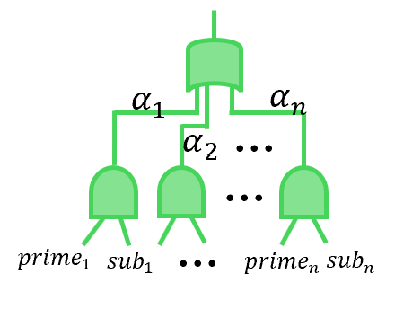
The image depicts a logic diagram consisting of multiple AND gates feeding into a single OR gate. The inputs to the AND gates are labeled as "prime" and "sub", with numerical subscripts. The outputs of the AND gates are labeled with alpha symbols, also with numerical subscripts. The entire diagram is rendered in a light green color.
### Components/Axes
* **Logic Gates:** The diagram uses two types of logic gates: AND gates and an OR gate.
* **Inputs:** The inputs to the AND gates are labeled as "prime₁ sub₁ ... primeₙ subₙ".
* **Outputs:** The outputs of the AND gates are labeled as "α₁", "α₂", ..., "αₙ".
* **Connectors:** Lines connect the outputs of the AND gates to the inputs of the OR gate.
### Detailed Analysis
* **AND Gates:** There are multiple AND gates, each with two inputs labeled "primeᵢ" and "subᵢ", where 'i' ranges from 1 to 'n'. The AND gates are represented by a curved shape with two inputs and one output.
* **OR Gate:** A single OR gate is present at the top of the diagram. It has multiple inputs, each connected to the output of an AND gate. The OR gate is represented by a curved shape with multiple inputs and one output.
* **Input Labels:** The inputs to the AND gates are labeled as follows:
* "prime₁" and "sub₁" for the first AND gate.
* "primeₙ" and "subₙ" for the last AND gate.
* The inputs for the intermediate AND gates are represented by ellipsis (...).
* **Output Labels:** The outputs of the AND gates are labeled as follows:
* "α₁" for the first AND gate.
* "α₂" for the second AND gate.
* "αₙ" for the last AND gate.
* The outputs for the intermediate AND gates are represented by ellipsis (...).
* **Connections:** The outputs "α₁", "α₂", ..., "αₙ" are connected to the inputs of the OR gate.
### Key Observations
* The diagram represents a logic network where the outputs of multiple AND gates are combined using an OR gate.
* The inputs to the AND gates are labeled as "prime" and "sub", suggesting a relationship between these inputs.
* The number of AND gates is 'n', as indicated by the subscripts on the input and output labels.
### Interpretation
The diagram likely represents a logical function where the OR gate's output is true if at least one of the AND gates outputs a true value. Each AND gate requires both its "prime" and "sub" inputs to be true in order to output a true value. The overall function could be interpreted as a condition where at least one "prime" and its corresponding "sub" condition must be met for the final output to be true. The ellipsis indicate that the pattern continues for an unspecified number of AND gates.