## System Diagram: Secure Deployment Architecture
### Overview
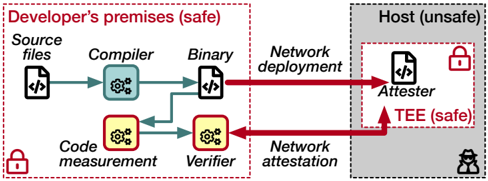
The image illustrates a secure deployment architecture, contrasting a "safe" developer's environment with an "unsafe" host environment. It depicts the flow of code from source files to a binary, and then to an attester within a trusted execution environment (TEE) on the host. The diagram highlights the processes of code measurement, verification, and network attestation to ensure security.
### Components/Axes
* **Regions:**
* **Developer's premises (safe):** Enclosed in a red dashed rectangle, located on the left side of the diagram. A red padlock icon is present in the bottom-left corner of this region.
* **Host (unsafe):** Enclosed in a gray dashed rectangle, located on the right side of the diagram. A red padlock icon is present inside a smaller red dashed rectangle labeled "TEE (safe)" within the host environment. A black hacker icon is present in the bottom-right corner of this region.
* **Processes/Components:**
* **Source files:** Represented by a file icon with "</>" inside. Located in the top-left of the "Developer's premises" region.
* **Compiler:** Represented by a blue gear icon. Located to the right of "Source files".
* **Binary:** Represented by a file icon with "</>" inside. Located to the right of "Compiler".
* **Network deployment:** Text label above the red arrow going from "Binary" to "Attester".
* **Code measurement:** Represented by a yellow gear icon. Located below "Compiler".
* **Verifier:** Represented by a yellow gear icon. Located to the right of "Code measurement".
* **Network attestation:** Text label below the red arrow going from "Verifier" to "Attester".
* **Attester:** Represented by a file icon with "</>" inside. Located in the "Host" region.
* **TEE (safe):** Trusted Execution Environment, enclosed in a red dashed rectangle within the "Host" region.
### Detailed Analysis
* **Flow:**
* Source files are processed by the Compiler, resulting in a Binary.
* The Binary is deployed to the Attester via "Network deployment" (red arrow).
* Independently, the Source files are subjected to Code measurement, and then processed by the Verifier.
* The Verifier performs "Network attestation" to the Attester (red arrow).
* **Data Points/Connections:**
* A green arrow connects "Source files" to "Compiler".
* A green arrow connects "Compiler" to "Binary".
* A green arrow connects "Source files" to "Code measurement".
* A green arrow connects "Code measurement" to "Verifier".
* A red arrow connects "Binary" to "Attester" (Network deployment).
* A red arrow connects "Verifier" to "Attester" (Network attestation).
### Key Observations
* The diagram clearly separates the "safe" development environment from the "unsafe" host environment.
* The use of a TEE within the host environment provides a secure execution space for the Attester.
* The processes of code measurement, verification, and network attestation are crucial for ensuring the integrity and trustworthiness of the deployed binary.
* The red arrows indicate network communication, highlighting potential attack vectors.
### Interpretation
The diagram illustrates a security-focused deployment strategy. By performing code measurement and verification within the trusted "Developer's premises," the system aims to ensure that only verified and untampered code is deployed to the "unsafe" host environment. The TEE provides an additional layer of security by isolating the Attester from the rest of the host system. The network attestation process further validates the integrity of the deployed code. This architecture is designed to mitigate risks associated with deploying code to potentially compromised environments. The presence of the hacker icon in the "Host (unsafe)" region emphasizes the importance of these security measures.