## Simulink Diagram: Require Block and Subsystem Components
### Overview
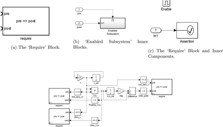
The image presents a Simulink diagram illustrating the 'Require' block, its inner components, and an 'Enabled Subsystem' block. It also shows a more complex system involving multiple blocks and feedback loops, likely demonstrating a control system or algorithm.
### Components/Axes
* **(a) The 'Require' Block:** A rectangular block labeled "require" with two input/output ports labeled "pre" (top-left) and "post" (bottom-left). Inside the block, the text "pre => post" is displayed.
* **(b) 'Enabled Subsystem' Inner Blocks:** Shows a subsystem block labeled "Enabled Subsystem". It has an input port labeled "In1" connected to an input signal "2 post" and an output signal "1 pre". There is also an "Enable" input at the top.
* **(c) The 'Require' Block and Inner Components:** Shows an input port labeled "1 In1" connected to an "Assertion" block, which contains a checkmark symbol.
* **Complex System Diagram:** A more complex diagram containing several blocks, including:
* A Gain block with a value of "0.9" and input "x".
* A Delay block labeled "1/z x_old".
* A 'Require' block labeled "require1" with "pre" and "post" ports and the text "pre => post" inside.
* A 'Not Equal To Zero' block labeled "Not_zero_x2" with the condition "~= 0".
* A 'Zero' block labeled "Zero_x" with the condition "== 0".
* A 'V(x)' block with outputs ">0" and "Positive_V(x)".
* A Delay block labeled "1/z V(x)_old".
* A Gain block with a value of "-1" labeled "neg".
* A Sum block labeled "Difference".
* A 'Less Than Zero' block labeled "Desc_grad" with the condition "< 0".
* Another 'Require' block labeled "require" with "pre" and "post" ports and the text "pre => post" inside.
* A 'Require' block labeled "require2" with "pre" and "post" ports and the text "pre => post" inside.
* A 'Zero' block labeled "Zero_V(x)" with the condition "== 0".
* A 'Not Equal To Zero' block labeled "Not_zero_x" with the condition "~= 0".
### Detailed Analysis or Content Details
* **Require Block:** The 'Require' block seems to enforce a condition where 'pre' must imply 'post'.
* **Enabled Subsystem:** The 'Enabled Subsystem' block is a standard Simulink block that executes its contents only when the enable signal is active.
* **Assertion Block:** The 'Assertion' block checks if a condition is true and halts the simulation if it is false.
* **Complex System Diagram:**
* The signal "x" is multiplied by 0.9 and fed into a delay block.
* The output of the delay block "x_old" is used in the "V(x)" block.
* The "V(x)" block has two outputs: "Positive_V(x)" and ">0".
* The "Positive_V(x)" output is connected to a 'Zero' block labeled "Zero_V(x)".
* The output of the "V(x)" block is also fed into a delay block "V(x)_old".
* The output of the delay block "V(x)_old" is multiplied by -1.
* The output of the "-1" block and the "V(x)" block are fed into a Sum block labeled "Difference".
* The output of the "Difference" block is fed into a 'Less Than Zero' block labeled "Desc_grad".
* The outputs of the 'Not Equal To Zero' blocks and 'Zero' blocks are connected to the 'pre' ports of the 'Require' blocks.
* The outputs of the 'Less Than Zero' block and the ">0" output of the "V(x)" block are connected to the 'pre' ports of the 'Require' blocks.
### Key Observations
* The 'Require' block is used to enforce conditions within the Simulink model.
* The complex system diagram appears to implement a control algorithm or a system with feedback loops.
* The 'Not Equal To Zero' and 'Zero' blocks are used to check if signals are zero or non-zero.
* The 'Less Than Zero' block is used to check if a signal is negative.
### Interpretation
The diagram illustrates the use of the 'Require' block in Simulink to enforce conditions and constraints within a model. The complex system diagram demonstrates a more elaborate system, possibly a control system, where the 'Require' blocks are used to ensure that certain conditions are met during the simulation. The feedback loops and various blocks suggest a dynamic system where the behavior is influenced by past states and current inputs. The use of 'Not Equal To Zero', 'Zero', and 'Less Than Zero' blocks indicates that the system's behavior is dependent on the sign and magnitude of certain signals.