\n
## Diagram: System Block Diagrams with Assertions
### Overview
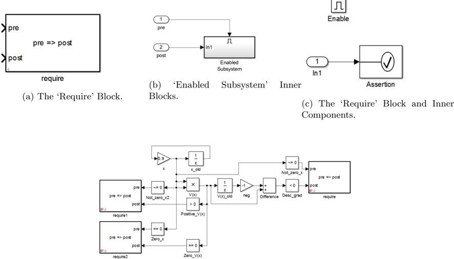
The image presents a series of block diagrams illustrating a system with pre- and post-conditions, requirements, and assertions. The diagrams appear to be related to a control system or a mathematical model, potentially for verifying system behavior. The diagrams are labeled (a), (b), and (c), and a more complex diagram is shown at the bottom.
### Components/Axes
The diagrams utilize blocks representing system components, arrows indicating signal flow, and labels denoting conditions (pre, post, require) and signals (Enable, In1, x, V(x), neg, etc.). There are no axes in the traditional sense, but the diagrams are spatially organized to show relationships between components.
### Detailed Analysis or Content Details
**(a) The ‘Require’ Block:**
* A rectangular block labeled "require".
* Input labeled "pre" on the left side.
* Output labeled "post" on the right side.
* Text within the block: "pre => post".
**(b) ‘Enabled Subsystem’ Inner Blocks:**
* Block 1: Labeled "pre", input "1".
* Block 2: Labeled "post", input "2".
* Arrow from Block 1 to "In1" of "Enabled Subsystem".
* Arrow from "Enabled Subsystem" to Block 2.
* A pulse signal labeled "Enable" is connected to the "Enabled Subsystem".
**(c) The ‘Require’ Block and Inner Components:**
* Block labeled "In1", input "1".
* Output of "In1" connects to an Assertion block (a circle with a checkmark inside).
**Bottom Diagram (Complex System):**
This diagram is significantly more complex, showing a network of interconnected blocks and signals. Here's a breakdown:
* **Left Side:** Two blocks labeled "require1" and "require2".
* "require1": Input "pre", output "post", text "pre => post".
* "require2": Input "pre", output "post", text "pre => post".
* **Central Section:** A series of interconnected blocks:
* Constant block with value "0.9" outputting "x".
* Block labeled "x_old".
* Multiplication block with inputs "x" and "V(x)", outputting a signal.
* Block labeled "V(x)_old".
* Summing junction with inputs "V(x)_old" and "neg", outputting a signal.
* Block labeled "Difference Desc_grad".
* Block labeled "Not_zero_x". Input "pre", output "post", text "pre => post".
* **Right Side:**
* Block labeled "Not_zero_x2". Input "pre", output "post", text "pre => post".
* Block labeled "Positive_V(x)". Input "0", output "0".
* Block labeled "Zero_V(x)". Input "0", output "0".
* Block labeled "require". Input "pre", output "post", text "pre => post".
### Key Observations
* The diagrams consistently use "pre" and "post" to denote pre- and post-conditions, suggesting a formal verification or modeling approach.
* The "require" blocks indicate requirements that must be met for the system to function correctly.
* The assertion block in diagram (c) suggests a check to ensure the system meets its specifications.
* The complex diagram at the bottom appears to represent a control loop or iterative process, with feedback and calculations involving "x" and "V(x)".
* The blocks labeled "Positive_V(x)" and "Zero_V(x)" suggest conditions related to the value of V(x).
### Interpretation
The diagrams illustrate a system design process that emphasizes formal verification and requirement satisfaction. The use of pre- and post-conditions, requirements blocks, and assertions indicates a rigorous approach to ensuring the system behaves as intended. The complex diagram at the bottom likely represents a specific algorithm or control strategy, where the values of "x" and "V(x)" are iteratively adjusted to meet certain criteria. The "require" blocks and assertions serve as safety nets, ensuring that the system remains within acceptable bounds and meets its specified requirements. The diagram is not providing numerical data, but rather a structural representation of a system and its verification process. The diagram is a visual representation of a logical system, and the relationships between the blocks are crucial for understanding the system's behavior. The use of "pre" and "post" conditions suggests a focus on input-output relationships and the preservation of certain properties throughout the system.