## Technical Diagram: Simulink Block Diagrams for Formal Verification Components
### Overview
The image displays a composite of four technical diagrams illustrating components and structures for formal verification within a model-based design environment (likely Simulink). The diagrams show block-based models with signal flows, logical operators, and subsystems. The content is presented in English.
### Components/Axes
The image is segmented into four distinct regions:
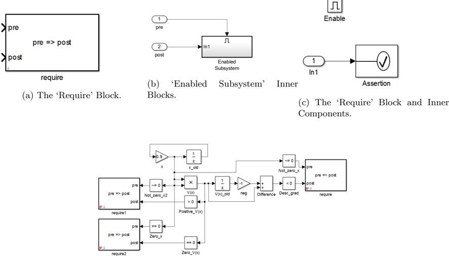
1. **Top-Left (a):** A single block labeled "require".
2. **Top-Center (b):** An "Enabled Subsystem" block with inner components.
3. **Top-Right (c):** An "Assertion" block connected to an input.
4. **Bottom (Unlabeled):** A larger, interconnected system diagram combining multiple "require" blocks and other logic.
**Textual Elements and Labels:**
* **Block Labels:** `require`, `Enabled Subsystem`, `Assertion`.
* **Port Labels:** `pre`, `post`, `In1`, `Enable`.
* **Signal/Variable Names:** `x`, `x_old`, `V(x)`, `V(x)_old`, `neg`, `Difference`, `Desc_grad`, `Not_zero_x`, `Not_zero_x2`, `Positive_V(x)`, `Zero_x`, `Zero_V(x)`.
* **Mathematical/Logical Operators:** `=>` (implies), `== 0`, `> 0`, `< 0`, `≠ 0`, `X` (multiplication), `-1`, `1/z` (unit delay), `0.9`.
* **Caption Text:**
* (a) The ‘Require’ Block.
* (b) ‘Enabled Subsystem’ Inner Blocks.
* (c) The ‘Require’ Block and Inner Components.
### Detailed Analysis / Content Details
**Region (a): The ‘Require’ Block**
* **Position:** Top-left quadrant.
* **Description:** A rectangular block with two input ports on the left (`pre`, `post`) and one output port on the bottom (`require`). The block's internal text reads `pre => post`, indicating it models a logical implication (if `pre` is true, then `post` must be true).
**Region (b): ‘Enabled Subsystem’ Inner Blocks**
* **Position:** Top-center.
* **Description:** Shows the internal structure of an enabled subsystem.
* An `Enable` port (labeled with a pulse icon) connects to the subsystem's control input.
* Two input ports: `1 pre` and `2 post`.
* These feed into a block labeled `In1`, which is inside a larger block labeled `Enabled Subsystem`.
**Region (c): The ‘Require’ Block and Inner Components**
* **Position:** Top-right.
* **Description:** Depicts a simplified view of a requirement check.
* An input port `1 In1` connects to a block containing a checkmark inside a circle, labeled `Assertion`.
* An `Enable` port (pulse icon) is shown above, suggesting the assertion is conditional.
**Bottom Diagram: Integrated Verification System**
* **Position:** Spans the lower half of the image.
* **Description:** A complex signal flow diagram integrating the components above.
* **Left Side:** Two instances of the `require` block (`require1`, `require2`). Each has `pre` and `post` inputs and a `require` output.
* **Signal Processing Path:**
1. A signal `x` is multiplied by `0.9` and fed into a unit delay (`1/z`), producing `x_old`.
2. `x` and `x_old` are compared (`≠ 0`) to generate `Not_zero_x2`.
3. `x` is also multiplied (`X`) with another signal to produce `V(x)`.
4. `V(x)` goes through a unit delay to become `V(x)_old`.
5. `V(x)_old` is multiplied by `-1` (`neg`) and added (`+`) to `V(x)` to compute `Difference`.
6. `Difference` is checked against `< 0` to produce `Desc_grad`.
* **Condition Generation:**
* `Not_zero_x` is generated from `x` via a `≠ 0` check.
* `Positive_V(x)` is generated from `V(x)` via a `> 0` check.
* `Zero_x` is generated from `x` via a `== 0` check.
* `Zero_V(x)` is generated from `V(x)` via a `== 0` check.
* **Final Requirement Block:** The signals `Not_zero_x` and `Desc_grad` are fed as `pre` and `post` inputs, respectively, into a final `require` block on the far right.
### Key Observations
1. **Modular Design:** The system is built from reusable blocks (`require`, `Enabled Subsystem`, `Assertion`).
2. **Signal Flow:** The bottom diagram shows a clear left-to-right data flow, processing an input `x` to compute a value `V(x)`, its difference, and a gradient condition, which are then checked against a formal requirement.
3. **Temporal Logic:** The use of unit delay blocks (`1/z`) indicates the system operates on discrete time steps, comparing current and previous values (`x` vs. `x_old`, `V(x)` vs. `V(x)_old`).
4. **Condition Hierarchy:** Multiple logical conditions (`Not_zero_x`, `Positive_V(x)`, `Zero_x`, `Zero_V(x)`) are generated in parallel from the core signals.
### Interpretation
This diagram set illustrates a framework for embedding formal verification assertions directly into a dynamic system model. The `require` block is the core component, encapsulating the specification `pre => post` (a precondition must imply a postcondition).
The bottom diagram demonstrates a practical application: verifying a property of a discrete-time system. It appears to be checking a **descent condition**. The logic suggests the requirement is: **"If `x` is not zero (`Not_zero_x`), then the difference in `V(x)` must be negative (`Desc_grad`)."** This is a common pattern in optimization or stability analysis, where a Lyapunov-like function `V(x)` should decrease over time (`Difference < 0`) when the state `x` is non-zero.
The inclusion of `Enabled Subsystem` and `Assertion` blocks indicates this verification logic can be conditionally activated and used to trigger runtime errors or halt simulation if the formal requirement is violated. This bridges the gap between model-based design and formal methods, allowing engineers to validate system properties during simulation.