## Diagram: Formal System Verification Components
### Overview
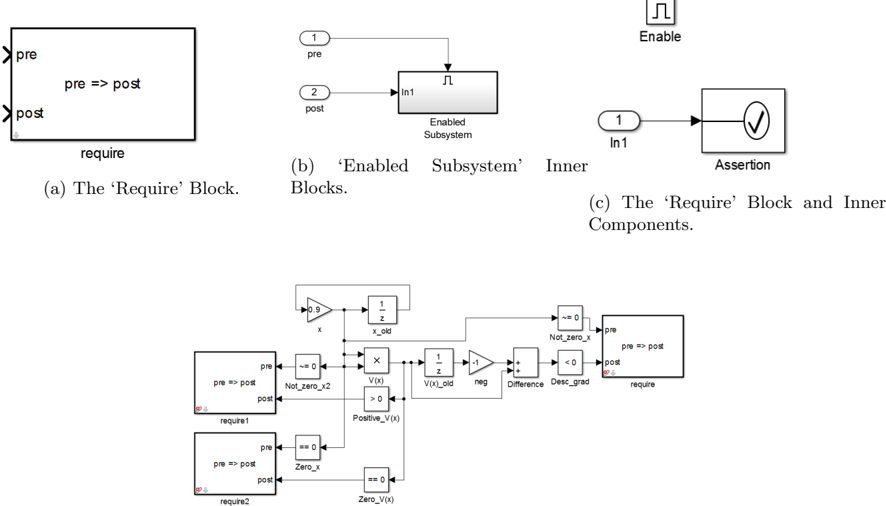
The image depicts three interconnected diagrams illustrating components of a formal verification system. These include precondition/postcondition blocks, enabled subsystem logic, and assertion mechanisms. A complex state machine diagram at the bottom integrates these elements with mathematical expressions and control flow.
### Components/Axes
1. **Diagram (a): 'Require' Block**
- Contains labeled boxes: `pre`, `post`, and `require`
- Text: `pre => post` (precondition implies postcondition)
- Arrows indicate flow from `pre` to `post`
2. **Diagram (b): 'Enabled Subsystem' Inner Blocks**
- Step 1: `pre` → `post` with arrow
- Step 2: `post` → `Enabled Subsystem` block
- Includes `In1` (input) and `In` (function/operation)
- "Enable" label at top indicates activation condition
3. **Diagram (c): Combined 'Require' and Inner Components**
- Integrates precondition/postcondition with `Enabled Subsystem` and `Assertion`
- `In1` connects to `Assertion` block with checkmark (✓)
- "Assertion" validates postcondition satisfaction
4. **Complex State Machine Diagram**
- Contains:
- Precondition/Postcondition blocks (`pre => post`)
- Mathematical expressions: `x_old`, `V(x)`, `Positive_V(x)`, `Zero_x`
- Control flow elements: `Not_zero_x`, `Difference`, `Desc_grad`
- State transitions with conditions (e.g., `V(x) > 0` → `Positive_V(x)`)
- Requirement blocks (`require1`, `require2`)
### Detailed Analysis
- **Precondition/Postcondition Flow**: All diagrams emphasize `pre => post` relationships, suggesting formal verification of system behavior.
- **Enabled Subsystem Logic**: Stepwise processing from input (`In1`) through enabled subsystem to output (`post`).
- **Assertion Mechanism**: Checkmark symbolizes successful validation of postconditions.
- **State Machine Complexity**: The bottom diagram shows nested conditions and state transitions, including:
- Zero-checking (`Not_zero_x`, `Zero_x`)
- Value validation (`V(x) > 0` → `Positive_V(x)`)
- Gradient descent (`Desc_grad`) and difference calculations
### Key Observations
1. **Modular Design**: Components are isolated (e.g., `require1`, `require2`) but interconnected through control flow.
2. **Formal Verification Focus**: Preconditions, postconditions, and assertions align with formal methods for software correctness.
3. **Mathematical Rigor**: Expressions like `V(x)` and `Positive_V(x)` imply quantitative verification criteria.
4. **Input Handling**: `In1` appears in both subsystem diagrams, suggesting standardized input processing.
### Interpretation
This system appears to implement a formal verification framework for software or hardware systems. The 'Require' blocks establish behavioral contracts (`pre => post`), while the enabled subsystem processes inputs under specific conditions. The complex state machine at the bottom likely represents the detailed logic for:
- **State Transitions**: Managing system states based on mathematical conditions (e.g., positivity checks).
- **Verification Assertions**: Validating that postconditions hold after subsystem execution.
- **Input Validation**: Ensuring inputs (`In1`) meet requirements before processing.
The diagrams collectively suggest a layered approach to verification, combining high-level contracts with granular mathematical checks. The checkmark in the assertion block implies automated validation of system correctness, critical for safety-critical systems or formal proofs.