## Diagram: Matrix Multiplication with Memory Hierarchy (Cache/Register)
### Overview
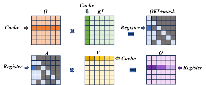
The image is a technical diagram illustrating a two-step matrix multiplication process, likely representing an optimized computation kernel (such as an attention mechanism in transformers). It visually maps how data is moved between different levels of memory hierarchy—specifically **Cache** and **Register**—during the computation. The diagram is divided into two horizontal rows, each depicting a matrix multiplication operation with specific data access patterns highlighted.
### Components/Axes
The diagram consists of six primary matrices, each represented as a 5x5 grid of cells. The matrices are labeled with mathematical notation:
- **Top Row (Left to Right):**
1. **Q**: A matrix with an orange-highlighted row. An arrow labeled **"Cache"** points to this row.
2. **×** (Multiplication symbol)
3. **Kᵀ**: A matrix with a green-highlighted column. An arrow labeled **"Cache"** points to this column.
4. **=** (Equals symbol)
5. **QKᵀ+mask**: The resulting matrix. It has a blue-highlighted cell in the top-left and a diagonal pattern of gray cells. An arrow labeled **"Register"** points to the blue cell.
- **Bottom Row (Left to Right):**
1. **A**: A matrix with a blue-highlighted cell in the top-left and a diagonal pattern of gray cells (identical to the *QKᵀ+mask* matrix above). An arrow labeled **"Register"** points to the blue cell.
2. **×** (Multiplication symbol)
3. **V**: A matrix with a yellow-highlighted row. An arrow labeled **"Cache"** points to this row.
4. **=** (Equals symbol)
5. **O**: The final output matrix. It has a purple-highlighted row. An arrow labeled **"Register"** points to this row.
**Spatial Grounding:**
- The **"Cache"** labels are positioned to the left of the *Q* matrix and above the *Kᵀ* matrix in the top row, and to the right of the *V* matrix in the bottom row.
- The **"Register"** labels are positioned to the right of the *QKᵀ+mask* matrix in the top row, and to the left of the *A* matrix and to the right of the *O* matrix in the bottom row.
- The highlighted rows/columns/cells are consistently colored across the diagram to indicate data locality.
### Detailed Analysis
The diagram breaks down the computation `O = (QKᵀ + mask) * V` into two distinct multiplication steps, emphasizing memory access patterns:
1. **Step 1: Compute `QKᵀ + mask`**
- **Input Data from Cache:** A single **row** of matrix **Q** (orange) and a single **column** of matrix **Kᵀ** (green) are fetched from the cache.
- **Computation:** These are multiplied (dot product) to produce a single scalar value.
- **Output to Register:** The result, after adding a mask (implied by the label `QKᵀ+mask`), is stored in a **register** (blue cell). The diagonal gray pattern in the output matrix suggests this operation is repeated for multiple positions, with the blue cell representing one computed element.
2. **Step 2: Compute Final Output `O`**
- **Input Data from Register & Cache:** The previously computed scalar value (blue cell in matrix **A**, which is `QKᵀ+mask`) is held in a **register**. A single **row** of matrix **V** (yellow) is fetched from the **cache**.
- **Computation:** The scalar from the register is multiplied with the entire row from *V*.
- **Output to Register:** The resulting row is stored in a **register** (purple row in matrix **O**). This implies the entire output row is accumulated in fast register memory.
**Component Isolation:**
- **Header Region:** Contains the labels for the first multiplication (`Q`, `Kᵀ`, `QKᵀ+mask`) and the "Cache"/"Register" annotations for Step 1.
- **Main Chart Region:** The two rows of matrix grids and operations.
- **Footer Region:** Contains the labels for the second multiplication (`A`, `V`, `O`) and the "Cache"/"Register" annotations for Step 2.
### Key Observations
1. **Memory Hierarchy Optimization:** The diagram explicitly shows a strategy to minimize slow memory access. Data is loaded from **Cache** (slower than registers but faster than main memory) in large chunks (rows/columns), while intermediate and final results are kept in **Registers** (the fastest memory).
2. **Data Reuse Pattern:** In Step 1, one row of *Q* and one column of *Kᵀ* are used. In Step 2, one scalar from the intermediate result is reused across an entire row of *V*. This is a classic pattern for optimizing matrix multiplication on hardware with limited register files.
3. **Visual Consistency:** The color coding is consistent: Orange/Green for cache-loaded inputs in step 1, Blue for register-held intermediate, Yellow for cache-loaded input in step 2, and Purple for register-held final output.
4. **Implicit Masking:** The label `QKᵀ+mask` indicates an additive mask is applied to the result of `QKᵀ`, a common operation in attention mechanisms to prevent attending to future tokens.
### Interpretation
This diagram is a **Peircean icon** representing the physical computation flow of an optimized kernel. It doesn't show numerical data but rather the **architectural strategy** for efficient computation.
- **What it demonstrates:** It illustrates how a complex matrix operation is decomposed into smaller, hardware-friendly steps that maximize data locality. The goal is to keep the compute units (which operate on registers) constantly fed with data from the cache, minimizing stalls caused by waiting for data from slower memory levels.
- **Relationship between elements:** The two rows are sequential. The output of the first multiplication (`QKᵀ+mask`, held in register `A`) becomes a direct input to the second multiplication. The "Cache" and "Register" labels are not just annotations; they define the **source and sink** of data for each computational step, revealing the underlying hardware-aware algorithm design.
- **Notable implication:** This pattern is characteristic of high-performance implementations of operations like **scaled dot-product attention** on GPUs or specialized AI accelerators. The diagram serves as a blueprint for understanding or implementing such a kernel, emphasizing that performance is dictated not just by the arithmetic but by the orchestration of data movement through the memory hierarchy.