## Diagram: ProbTime Compilation Process
### Overview
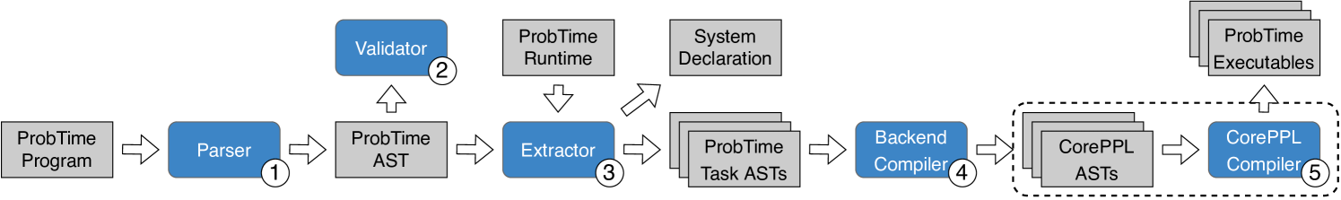
The image is a diagram illustrating the compilation process of ProbTime, a programming language. It shows the flow of data and transformations from the initial ProbTime Program to the final CorePPL Executables, highlighting key components like Parser, Validator, Extractor, Backend Compiler, and CorePPL Compiler.
### Components/Axes
* **Nodes:** The diagram consists of rectangular nodes representing different stages or components in the compilation process. These nodes are labeled with the names of the components and their associated data structures. Some nodes are colored blue, while others are gray.
* **Arrows:** Arrows indicate the flow of data and control between the components.
* **Numbers:** Each blue node has a number in a circle next to it, indicating the order of operations.
### Detailed Analysis
1. **ProbTime Program:** The process begins with a "ProbTime Program" represented by a gray rectangle on the left.
2. **Parser (1):** The "ProbTime Program" is fed into the "Parser," a blue rectangle. The number "1" in a circle is next to the Parser.
3. **ProbTime AST:** The Parser outputs "ProbTime AST" (Abstract Syntax Tree), represented by a gray rectangle.
4. **Validator (2):** The "ProbTime AST" is fed into the "Validator," a blue rectangle. The number "2" in a circle is next to the Validator.
5. **ProbTime Runtime:** A "ProbTime Runtime" gray rectangle is positioned above the "Extractor" and feeds into it.
6. **System Declaration:** A "System Declaration" gray rectangle is positioned above the "ProbTime Task ASTs" and feeds into the "Extractor".
7. **Extractor (3):** The "ProbTime AST," "ProbTime Runtime," and "System Declaration" are fed into the "Extractor," a blue rectangle. The number "3" in a circle is next to the Extractor.
8. **ProbTime Task ASTs:** The Extractor outputs "ProbTime Task ASTs," represented by a stack of gray rectangles.
9. **Backend Compiler (4):** The "ProbTime Task ASTs" are fed into the "Backend Compiler," a blue rectangle. The number "4" in a circle is next to the Backend Compiler.
10. **CorePPL ASTs:** The Backend Compiler outputs "CorePPL ASTs," represented by a stack of gray rectangles enclosed in a dashed rectangle.
11. **CorePPL Compiler (5):** The "CorePPL ASTs" are fed into the "CorePPL Compiler," a blue rectangle. The number "5" in a circle is next to the CorePPL Compiler.
12. **ProbTime Executables:** The CorePPL Compiler outputs "ProbTime Executables," represented by a stack of gray rectangles.
### Key Observations
* The diagram illustrates a sequential process, with data flowing from left to right.
* The blue rectangles represent active components (Parser, Validator, Extractor, Backend Compiler, CorePPL Compiler) that perform transformations on the data.
* The gray rectangles represent data structures (ProbTime Program, ProbTime AST, ProbTime Task ASTs, CorePPL ASTs, ProbTime Executables) that are passed between the components.
* The Validator, ProbTime Runtime, and System Declaration feed into the Extractor.
* The CorePPL ASTs and CorePPL Compiler are enclosed in a dashed rectangle, possibly indicating a related subsystem.
### Interpretation
The diagram depicts the compilation pipeline for ProbTime. The ProbTime Program is parsed and validated, then transformed into a series of Abstract Syntax Trees (ASTs). The Extractor combines the AST with runtime information and system declarations. The Backend Compiler then translates these ASTs into CorePPL ASTs, which are then compiled into ProbTime Executables by the CorePPL Compiler. The use of CorePPL as an intermediate representation suggests that ProbTime leverages CorePPL's capabilities for execution or further processing. The Validator step indicates a focus on ensuring the correctness and consistency of the ProbTime program before further compilation.