## Block Diagram: Computing Architecture for Processing Elements (PEs) and Memory Interface
### Overview
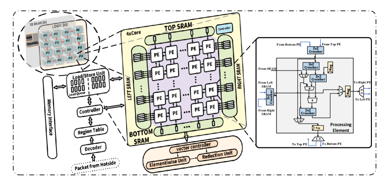
The diagram illustrates a modular computing architecture featuring a 4x4 array of Processing Elements (PEs) organized into four SRAM regions (Top, Bottom, Left, Right). The system includes a memory interface with a load/store unit, controller, region table, and decoder. Data flows from a "Packet from Hotside" through the memory interface into the SRAMs, which are interconnected via crossbars to enable parallel processing. A vector controller and reduction unit are positioned at the bottom for data aggregation and control.
---
### Components/Axes
#### Labels and Structure:
1. **Memory Interface**:
- **Load/Store Unit**: Interface for memory operations.
- **Controller**: Manages data flow between memory and SRAMs.
- **Region Table**: Maps data regions to SRAM locations.
- **Decoder**: Processes incoming packets from the hotside.
- **Packet from Hotside**: Input data stream.
2. **SRAM Regions**:
- **TOP SRAM**: 4x4 grid of PEs (green).
- **BOTTOM SRAM**: 4x4 grid of PEs (green).
- **LEFT SRAM**: 4x4 grid of PEs (green).
- **RIGHT SRAM**: 4x4 grid of PEs (green).
3. **Processing Elements (PEs)**:
- 16 PEs arranged in a 4x4 grid (purple squares).
- Connected via **2x2 Crossbar** networks (blue lines) for horizontal and vertical data routing.
4. **Control and Processing Units**:
- **Vector Controller**: Manages vector operations (orange).
- **Reduction Unit**: Aggregates results (orange).
5. **Crossbar Connections**:
- Horizontal and vertical crossbars link PEs across all SRAM regions.
---
### Detailed Analysis
#### Memory Interface Workflow:
- Data enters via the **Load/Store Unit** and is managed by the **Controller**.
- The **Region Table** directs data to specific SRAM regions.
- The **Decoder** processes incoming packets from the hotside before routing to SRAMs.
#### SRAM and PE Organization:
- Each SRAM region (Top, Bottom, Left, Right) contains a 4x4 grid of PEs.
- Crossbars enable direct communication between PEs in adjacent regions (e.g., Top SRAM to Bottom SRAM via vertical crossbars).
#### Vector Controller and Reduction Unit:
- The **Vector Controller** coordinates vector operations across PEs.
- The **Reduction Unit** aggregates results (e.g., summing values) from PEs.
---
### Key Observations
1. **Modular Design**: SRAM regions and PEs are organized into distinct blocks for scalability.
2. **Crossbar Efficiency**: 2x2 crossbars minimize routing complexity while enabling full connectivity.
3. **Parallelism**: 16 PEs allow simultaneous computation, with crossbars facilitating inter-PE communication.
4. **Control-Centric Architecture**: The vector controller and reduction unit centralize data aggregation and task management.
---
### Interpretation
This architecture prioritizes **high-throughput parallel processing** with minimal latency. The crossbar interconnects eliminate the need for sequential data routing, enabling efficient communication between PEs. The modular SRAM regions suggest scalability for larger systems, while the vector controller and reduction unit indicate support for vectorized operations (e.g., matrix multiplications, common in machine learning). The "Packet from Hotside" implies integration with a data source (e.g., a GPU or accelerator), highlighting the system's role in high-performance computing tasks. The absence of explicit clock or power management components suggests a focus on computational efficiency over energy optimization in this design.