## Diagram: Network Graph
### Overview
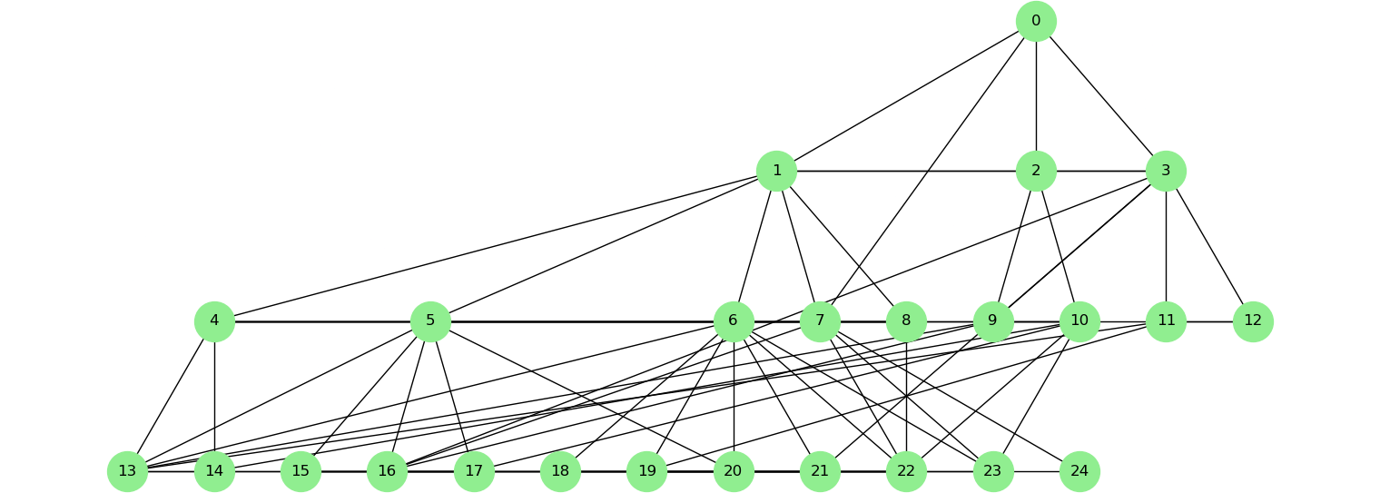
The image depicts a network graph consisting of 25 nodes (numbered 0 through 24) connected by directed edges. The nodes are represented as green circles. The graph appears to be a directed acyclic graph (DAG), as there are no visible cycles. The nodes are arranged roughly in two horizontal rows, with nodes 0-3 in the top row and nodes 4-24 in the bottom row.
### Components/Axes
There are no explicit axes or scales. The components are the nodes and the edges connecting them. Each node is labeled with a unique integer from 0 to 24. The edges are lines connecting the nodes, indicating a directed relationship.
### Detailed Analysis or Content Details
The graph's connections can be described as follows:
* **Node 0:** Connects to nodes 1, 2, and 3.
* **Node 1:** Connects to nodes 5, 6, 7, 8, 9, 10, and 11.
* **Node 2:** Connects to nodes 5, 6, 7, 8, 9, 10, and 11.
* **Node 3:** Connects to nodes 5, 6, 7, 8, 9, 10, and 11.
* **Node 4:** Connects to nodes 13, 14, 15, 16, 17, 18, 19, 20, 21, 22, 23, and 24.
* **Node 5:** Connects to nodes 13, 14, 15, 16, 17, 18, 19, 20, 21, 22, 23, and 24.
* **Node 6:** Connects to nodes 13, 14, 15, 16, 17, 18, 19, 20, 21, 22, 23, and 24.
* **Node 7:** Connects to nodes 13, 14, 15, 16, 17, 18, 19, 20, 21, 22, 23, and 24.
* **Node 8:** Connects to nodes 13, 14, 15, 16, 17, 18, 19, 20, 21, 22, 23, and 24.
* **Node 9:** Connects to nodes 13, 14, 15, 16, 17, 18, 19, 20, 21, 22, 23, and 24.
* **Node 10:** Connects to nodes 13, 14, 15, 16, 17, 18, 19, 20, 21, 22, 23, and 24.
* **Node 11:** Connects to nodes 13, 14, 15, 16, 17, 18, 19, 20, 21, 22, 23, and 24.
### Key Observations
* Nodes 0, 1, 2, and 3 are "source" nodes, as they only have outgoing edges.
* Nodes 13 through 24 are "sink" nodes, as they only have incoming edges.
* Nodes 4-11 act as intermediate nodes, receiving connections from nodes 0-3 and passing them on to nodes 13-24.
* The graph is highly interconnected, with a fan-out structure from the top row to the bottom row.
### Interpretation
This graph likely represents a workflow or dependency structure. Node 0 could represent an initial task or input, which branches into multiple parallel processes (nodes 1, 2, and 3). These processes then converge through intermediate nodes (4-11) to produce final outputs (nodes 13-24). The fact that each of nodes 1-3 connects to all of nodes 5-11 suggests that the intermediate nodes are performing similar operations on the outputs of the initial branches. The complete connectivity from nodes 4-11 to nodes 13-24 indicates that all intermediate processes contribute to all final outputs. This could represent a system where multiple inputs are processed through several stages to generate a diverse set of results. The graph's structure suggests a parallel processing architecture.