## Diagram: Conceptual Relationship Model
### Overview
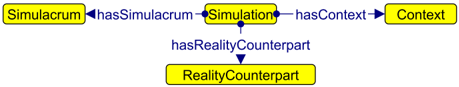
The diagram illustrates a conceptual relationship model involving four entities: **Simulacrum**, **Simulation**, **Context**, and **RealityCounterpart**. Arrows represent directional relationships between these entities, with labels describing the nature of the connections.
### Components/Axes
- **Nodes (Entities)**:
- Simulacrum
- Simulation
- Context
- RealityCounterpart
- **Edges (Relationships)**:
- `hasSimulacrum` (from Simulation to Simulacrum)
- `hasContext` (from Simulation to Context)
- `hasRealityCounterpart` (from Simulation to RealityCounterpart)
### Detailed Analysis
- **Simulacrum**: A standalone node with no incoming or outgoing edges.
- **Simulation**: Central node with three outgoing edges:
- `hasSimulacrum` → Simulacrum
- `hasContext` → Context
- `hasRealityCounterpart` → RealityCounterpart
- **Context**: Receives input from Simulation via `hasContext`.
- **RealityCounterpart**: Receives input from Simulation via `hasRealityCounterpart`.
### Key Observations
1. **Central Role of Simulation**: The Simulation node acts as a hub, connecting to three other entities.
2. **Unidirectional Flow**: All relationships are one-way, indicating a hierarchical or dependency-based structure.
3. **Isolation of Simulacrum**: Simulacrum is only referenced by Simulation and has no further connections.
### Interpretation
This diagram likely represents a theoretical framework for understanding how simulations (e.g., models, abstractions) relate to their real-world counterparts and contextual environments. The `hasRealityCounterpart` relationship suggests a focus on grounding simulations in tangible reality, while `hasContext` emphasizes situational or environmental dependencies. The isolated `Simulacrum` node may symbolize a purely abstract or detached concept within this model.
No numerical data or trends are present, as this is a conceptual diagram rather than a quantitative chart.