## System Diagram: Braking System
### Overview
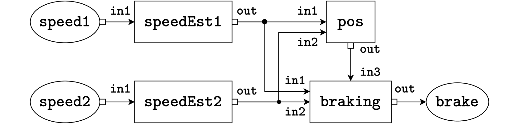
The image is a system diagram illustrating a braking system. It shows the flow of information and control signals between different components, including speed sensors, estimators, a position module, a braking module, and the final brake output.
### Components/Axes
* **Nodes:** The diagram contains nodes represented by ovals and rectangles. Ovals represent inputs and outputs (speed sensors and brake), while rectangles represent processing modules (speed estimators, position, and braking).
* **Connections:** Arrows indicate the flow of information between the nodes. Each arrow is labeled with an input or output name (e.g., "in1", "out").
### Detailed Analysis or ### Content Details
1. **speed1 (Oval, top-left):** Represents the first speed sensor input.
2. **speedEst1 (Rectangle, top-center):** Represents the first speed estimator module.
* Input: "in1" from "speed1"
* Output: "out" to "pos" (input "in1") and "braking" (input "in1")
3. **pos (Rectangle, top-right):** Represents the position module.
* Input: "in1" from "speedEst1"
* Input: "in2" from "speedEst2"
* Output: "out" to "braking" (input "in3")
4. **braking (Rectangle, bottom-right):** Represents the braking module.
* Input: "in1" from "speedEst1"
* Input: "in2" from "speedEst2"
* Input: "in3" from "pos"
* Output: "out" to "brake"
5. **brake (Oval, bottom-right):** Represents the final brake output.
6. **speed2 (Oval, bottom-left):** Represents the second speed sensor input.
7. **speedEst2 (Rectangle, bottom-center):** Represents the second speed estimator module.
* Input: "in1" from "speed2"
* Output: "out" to "pos" (input "in2") and "braking" (input "in2")
### Key Observations
* The system uses two speed sensors and estimators.
* The position module receives input from both speed estimators.
* The braking module receives input from both speed estimators and the position module.
### Interpretation
The diagram illustrates a redundant braking system that uses two speed sensors to improve reliability and accuracy. The speed estimators likely process the raw sensor data to filter noise and provide a more accurate speed estimate. The position module uses the speed estimates to determine the vehicle's position, which is then used by the braking module to calculate the appropriate braking force. The braking module integrates information from the speed estimators and the position module to control the final brake output. The redundancy in speed sensing and estimation suggests a safety-critical application where reliable braking is essential.