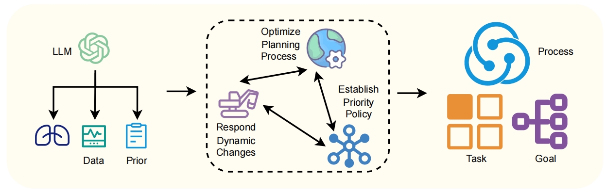
## Diagram: LLM-Driven Planning and Task Execution System
### Overview
The image is a conceptual diagram illustrating a workflow or system architecture where a Large Language Model (LLM) serves as the initial input source, feeding into a dynamic planning process, which ultimately produces structured outputs for task execution and goal achievement. The diagram flows from left to right, with a central, iterative processing loop.
### Components/Axes
The diagram is divided into three primary regions:
1. **Left Region (Input Source):**
* **Central Icon:** A green, stylized brain or network icon labeled **"LLM"**.
* **Outputs:** Three arrows point downward from the LLM icon to three distinct icons:
* **Left Icon:** A dark blue icon resembling lungs or a branching structure. No text label is directly attached.
* **Middle Icon:** A teal icon depicting a line chart on a monitor, labeled **"Data"**.
* **Right Icon:** A light blue clipboard icon, labeled **"Prior"**.
2. **Middle Region (Core Processing Loop):**
* This entire section is enclosed within a dashed, rounded rectangle, indicating a bounded process or system.
* **Three Interconnected Components:** Arrows form a triangular, bidirectional flow between three labeled items:
* **Top Component:** An icon of a globe with a gear, labeled **"Optimize Planning Process"**.
* **Bottom-Right Component:** A blue network or hub icon, labeled **"Establish Priority Policy"**.
* **Bottom-Left Component:** A purple icon of a person at a desk with a monitor, labeled **"Respond Dynamic Changes"**.
* **Flow:** A single arrow enters this dashed box from the left (from the LLM outputs). A single arrow exits to the right.
3. **Right Region (Output/Execution):**
* **Top Icon:** A large, blue, circular process icon (three interconnected nodes), labeled **"Process"**.
* **Bottom Icons:** Two icons sit side-by-side below the "Process" icon:
* **Left:** A 2x2 grid of orange squares, labeled **"Task"**.
* **Right:** A purple flowchart or decision tree icon, labeled **"Goal"**.
### Detailed Analysis
* **Spatial Grounding:** The legend/labels are placed directly adjacent to their corresponding icons. The "LLM" label is above its icon. "Data" and "Prior" are below theirs. The three process labels ("Optimize...", "Establish...", "Respond...") are positioned to the right of their respective icons within the central dashed box. "Process", "Task", and "Goal" are placed to the right of their icons.
* **Component Isolation & Flow:**
* **Input Stage:** The LLM provides foundational inputs categorized as an unlabeled resource (lungs icon), structured "Data", and existing "Prior" knowledge or policies.
* **Processing Stage:** These inputs feed into a dynamic, iterative loop. The system must "Optimize Planning Process" while simultaneously "Establish[ing] Priority Policy" and being able to "Respond [to] Dynamic Changes". The bidirectional arrows indicate continuous feedback and adjustment between these three activities.
* **Output Stage:** The refined output of this loop is a defined "Process" (the overarching method), which is then used to execute specific "Task"s (the grid) in service of achieving a defined "Goal" (the flowchart).
### Key Observations
1. **Iterative Core:** The central dashed box is not a linear step but a continuous, interconnected loop. Planning, policy, and response are not sequential but co-dependent and mutually informing.
2. **From Unstructured to Structured:** The flow moves from the broad, potentially unstructured intelligence of the LLM (left) through a refining, policy-driven process (middle) to produce concrete, actionable outputs: a process, tasks, and a goal (right).
3. **Role of "Prior":** The inclusion of "Prior" as a direct input from the LLM suggests the system explicitly incorporates pre-existing rules, knowledge, or constraints into the planning loop.
4. **Visual Metaphors:** Icons are used metaphorically: lungs for "vital input" or "branching possibilities," a globe with a gear for "global optimization," and a flowchart for a "goal" as a decision path.
### Interpretation
This diagram represents a sophisticated framework for autonomous or semi-autonomous agent operation. It posits that an LLM alone is insufficient for complex action; its output must be filtered through a dedicated, adaptive planning system.
* **The LLM as a Foundation, Not a Director:** The LLM provides raw material (data, priors, and another unlabeled resource, possibly "context" or "options"), but the actual decision-making logic resides in the middle loop. This separates generative capability from executive function.
* **The Necessity of Dynamic Policy:** The system's intelligence lies in the tension between optimization (efficiency), priority policy (rules/ethics), and dynamic response (adaptability). This triad ensures actions are both effective and compliant with changing conditions and constraints.
* **Actionable Outputs:** The ultimate purpose is not conversation but execution. The final outputs are operational: a defined process, discrete tasks, and a clear goal. This frames the entire system as a bridge between language understanding and real-world action.
* **Implied Feedback:** While not explicitly drawn, the "Respond Dynamic Changes" component implies a feedback loop from the execution of tasks and goals back into the planning process, creating a closed-loop system for continuous operation.
In essence, the diagram argues for an architecture where an LLM's capabilities are harnessed and governed by a separate, robust planning and policy engine to reliably achieve concrete objectives.