\n
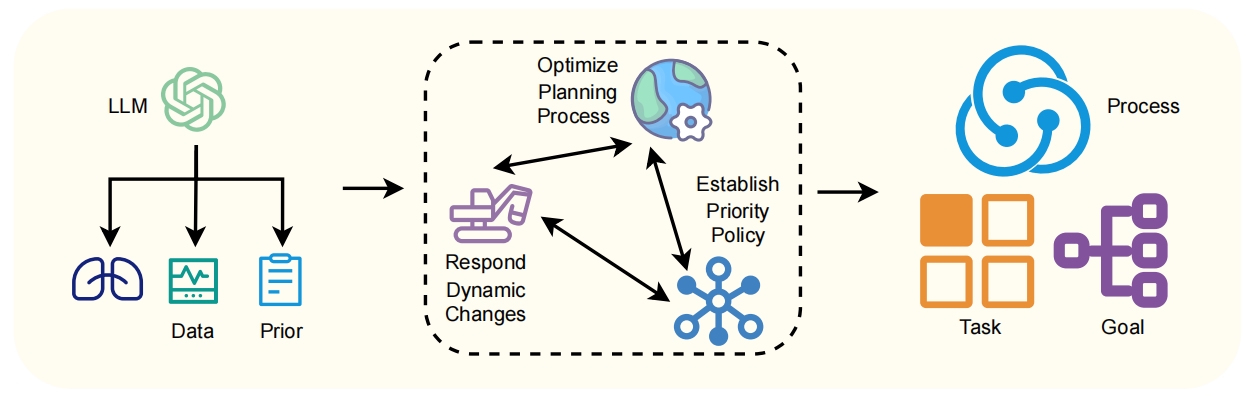
## Diagram: LLM-Driven Process Flow
### Overview
The image depicts a diagram illustrating a process flow driven by a Large Language Model (LLM). The LLM receives inputs of "Data" and "Prior" and feeds into a central processing stage, which then outputs "Task" and "Goal". The central processing stage is further broken down into sub-processes of "Optimize Planning Process", "Respond Dynamic Changes", and "Establish Priority Policy".
### Components/Axes
The diagram consists of the following components:
* **LLM:** Represented by a swirling, circular icon.
* **Data:** Represented by a graph-like icon.
* **Prior:** Represented by a document-like icon.
* **Optimize Planning Process:** Represented by a gear icon.
* **Respond Dynamic Changes:** Represented by a flag icon.
* **Establish Priority Policy:** Represented by a star-like icon.
* **Process:** Represented by a swirling, circular icon.
* **Task:** Represented by a grid of squares.
* **Goal:** Represented by a network of connected nodes.
The diagram uses arrows to indicate the flow of information and influence between these components. A dashed-line box encapsulates the "Optimize Planning Process", "Respond Dynamic Changes", and "Establish Priority Policy" components, visually grouping them as a central processing unit.
### Detailed Analysis or Content Details
The diagram shows a unidirectional flow:
1. The LLM receives input from "Data" and "Prior".
2. The LLM outputs to the central processing unit (encapsulated by the dashed box).
3. Within the central processing unit:
* The LLM output influences "Optimize Planning Process", "Respond Dynamic Changes", and "Establish Priority Policy".
* There is a cyclical flow between these three components, indicated by bidirectional arrows.
4. The central processing unit outputs to "Process".
5. "Process" then outputs to "Task" and "Goal".
There are no numerical values or specific data points present in the diagram. It is a conceptual representation of a process.
### Key Observations
The diagram emphasizes the LLM's role as a central driver of the process. The cyclical flow within the central processing unit suggests an iterative refinement or adjustment of planning, response, and prioritization. The final outputs, "Task" and "Goal", represent the actionable outcomes of the process.
### Interpretation
This diagram illustrates a system where an LLM is used to translate raw "Data" and pre-defined "Prior" into concrete "Task" assignments and overarching "Goal" definitions. The central processing unit, with its iterative loop, suggests a dynamic and adaptive system capable of responding to changing conditions and optimizing its planning process. The LLM doesn't directly produce tasks or goals, but rather informs a more complex internal process that does. The diagram highlights a modern approach to problem-solving, leveraging the capabilities of LLMs for intelligent automation and decision-making. The absence of specific details suggests this is a high-level architectural overview rather than a detailed implementation plan.