## Flowchart Diagram: State Transition Process with Conditional Outcomes
### Overview
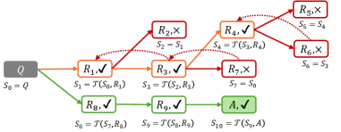
The diagram illustrates a sequential state transition process starting from an initial state `Q` (S₀) and progressing through a series of conditional transitions (R₁–R₉) to reach a final state `A` (S₁₀). Transitions are color-coded (orange, red, green) to indicate success, failure, or acceptance, with state transitions governed by rules R₁–R₉ and an acceptance rule `A`. The process includes loops, conditional branches, and terminal states.
---
### Components/Axes
- **Nodes**:
- **Initial State**: `Q` (labeled S₀).
- **Transition Rules**:
- R₁, R₂, R₃, R₄, R₅, R₆, R₇, R₈, R₉ (each with ✓ or × symbols).
- **Final State**: `A` (labeled S₁₀).
- **Edges**:
- Arrows represent transitions between states (e.g., S₀ → S₁ via R₁✓).
- Dotted arrows indicate conditional or alternative paths (e.g., S₃ → S₄ or S₇).
- **Legend**:
- **Orange**: Successful transitions (✓).
- **Red**: Failed transitions (×).
- **Green**: Accepted transitions (✓).
---
### Detailed Analysis
1. **Initial Path (S₀ → S₁ → S₂ → S₃)**:
- S₀ = Q → S₁ = T(S₀, R₁) via R₁✓ (orange).
- S₁ → S₂ = S₁ via R₂× (red, no state change).
- S₂ → S₃ = T(S₂, R₃) via R₃✓ (orange).
2. **Branching at S₃**:
- **Primary Path (S₃ → S₄ → S₅ → S₆)**:
- S₃ → S₄ = T(S₃, R₄) via R₄✓ (orange).
- S₄ → S₅ = S₄ via R₅× (red, no state change).
- S₅ → S₆ = S₅ via R₆× (red, no state change).
- **Alternative Path (S₃ → S₇ → S₀)**:
- S₃ → S₇ = S₀ via R₇× (red, loop back to initial state).
3. **Secondary Path (S₀ → S₈ → S₉ → S₁₀)**:
- S₀ → S₈ = T(S₇, R₈) via R₈✓ (green).
- S₈ → S₉ = T(S₈, R₉) via R₉✓ (green).
- S₉ → S₁₀ = T(S₉, A) via A✓ (green, final acceptance).
---
### Key Observations
1. **Success Path**: The only fully successful path to `A` (S₁₀) requires bypassing the initial loop (S₀ → S₁ → S₂ → S₃) and proceeding directly via R₈ and R₉ (green transitions).
2. **Failure Points**:
- R₂, R₅, R₆, and R₇ all fail (×), causing state stagnation or loops.
- R₇ creates a critical loop back to S₀, resetting progress.
3. **Conditional Logic**:
- Transitions like S₃ → S₄/S₇ suggest branching based on R₄’s outcome.
- R₈ and R₉ are prerequisites for reaching `A`, independent of earlier failures.
---
### Interpretation
This diagram models a **state machine with conditional acceptance criteria**. The process begins at `Q` (S₀) and attempts multiple transitions, but most fail (×), leading to stagnation or loops. The critical path to success (`A`, S₁₀) requires:
1. Avoiding the initial failed transitions (R₂, R₅, R₆, R₇).
2. Executing R₈ and R₉ successfully (green), which are only accessible after resetting via R₇× (S₃ → S₇ → S₀).
The use of color-coding and symbols (✓/×) emphasizes the binary outcomes of each rule. The loop from S₇ to S₀ introduces a **retry mechanism**, but only the secondary path (via R₈/R₉) avoids infinite recursion. This suggests a system where success depends on bypassing early failures and adhering to a specific subset of rules.