## Diagram: Bidirectional Network Flow with Ant Paths
### Overview
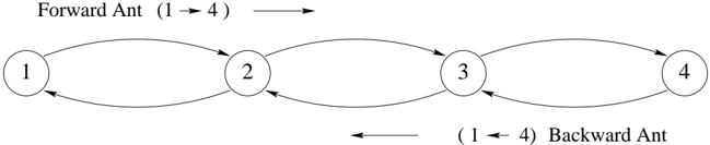
The image depicts a directed graph representing a network flow system with four nodes (1–4) arranged linearly. Two labeled paths ("Forward Ant" and "Backward Ant") traverse the network in opposite directions, with bidirectional arrows connecting adjacent nodes. The diagram emphasizes directional flow and symmetry in the system.
### Components/Axes
- **Nodes**: Four circular nodes labeled sequentially as 1, 2, 3, and 4.
- **Edges**: Bidirectional arrows between each pair of adjacent nodes (1↔2, 2↔3, 3↔4).
- **Labels**:
- **Forward Ant**: Arrow labeled "(1 → 4)" positioned above the nodes, pointing rightward.
- **Backward Ant**: Arrow labeled "(1 ← 4)" positioned below the nodes, pointing leftward.
- **Spatial Grounding**:
- Forward Ant arrow: Top-center alignment, spanning nodes 1 to 4.
- Backward Ant arrow: Bottom-center alignment, spanning nodes 4 to 1.
- Nodes are evenly spaced horizontally, with edges forming a "ladder" structure.
### Detailed Analysis
- **Node Connections**: Each node (1–4) has two bidirectional edges connecting it to its immediate neighbors (e.g., node 2 connects to 1 and 3).
- **Path Symmetry**: The Forward Ant path (1→2→3→4) and Backward Ant path (4→3→2→1) mirror each other, suggesting a reversible system.
- **Arrow Placement**: The Forward Ant arrow is visually dominant (top placement), while the Backward Ant arrow is subordinate (bottom placement), despite equal functional importance.
### Key Observations
1. **Bidirectional Flow**: All edges allow movement in both directions, enabling cyclical or oscillatory behavior.
2. **Path Labeling**: The ants’ paths are explicitly labeled with directional notation (→/←), emphasizing system reversibility.
3. **Node Uniformity**: Nodes lack unique identifiers beyond numbering, implying homogeneity in their roles.
### Interpretation
This diagram likely models a system where processes or entities (ants) traverse a linear sequence of stages (nodes) in both forward and backward directions. The bidirectional edges suggest:
- **Reversibility**: Steps can be undone or revisited (e.g., error correction, iterative refinement).
- **Symmetry**: The system treats forward and backward paths equally, though visual emphasis on the Forward Ant may imply prioritization in certain contexts.
- **Network Robustness**: Redundant pathways allow recovery from disruptions (e.g., if one edge fails, the alternate direction remains viable).
The absence of numerical data or probabilistic weights implies the diagram focuses on structural relationships rather than quantitative metrics. The ants’ labels anthropomorphize the flow, potentially simplifying complex dynamics for conceptual clarity.