## Diagram: Complex Instruction Breakdown
### Overview
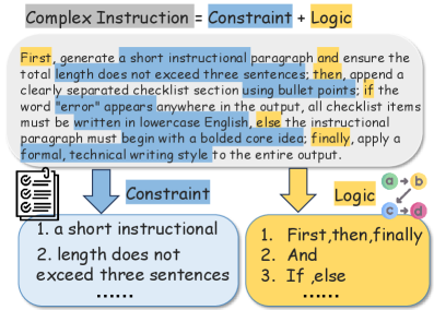
The image is a diagram illustrating the components of a "Complex Instruction." It breaks down a complex instruction into its constituent parts: Constraints and Logic. The diagram also provides an example of a complex instruction and how it relates to the constraints and logic components.
### Components/Axes
* **Header:** "Complex Instruction = Constraint + Logic" (Grey box)
* **Main Text Block:** A paragraph describing the complex instruction.
* **Constraint Block:** A blue rounded rectangle containing a list of constraints.
* **Logic Block:** A yellow rounded rectangle containing a list of logical steps.
* **Arrows:** Two blue arrows pointing from the main text block to the Constraint and Logic blocks.
* **Checklist Icon:** A checklist icon is present to the left of the Constraint block.
* **Logic Flow Diagram:** A small diagram showing a flow of logic from a to b and c to d.
### Detailed Analysis or ### Content Details
**1. Header:**
* Text: "Complex Instruction = Constraint + Logic"
* Background: Grey
**2. Main Text Block:**
* Text: "First, generate a short instructional paragraph and ensure the total length does not exceed three sentences; then, append a clearly separated checklist section using bullet points; if the word "error" appears anywhere in the output, all checklist items must be written in lowercase English, else the instructional paragraph must begin with a bolded core idea; finally, apply a formal, technical writing style to the entire output."
* Highlights: The words "First", "then", and "finally" are highlighted in yellow. The phrases "a short instructional paragraph", "total length does not exceed three sentences", "if the word 'error' appears anywhere in the output, all checklist items must be written in lowercase English", "else the instructional paragraph must begin with a bolded core idea", and "apply a formal, technical writing style to the entire output" are highlighted in blue.
**3. Constraint Block:**
* Label: "Constraint" (Blue box)
* Content:
1. "a short instructional"
2. "length does not exceed three sentences"
3. "......" (Indicates more constraints exist but are not listed)
**4. Logic Block:**
* Label: "Logic" (Yellow box)
* Content:
1. "First, then, finally"
2. "And"
3. "If, else"
4. "......" (Indicates more logic steps exist but are not listed)
**5. Logic Flow Diagram:**
* Diagram: A simple flow diagram with nodes labeled "a", "b", "c", and "d".
* Flow: "a" -> "b", "c" -> "d"
### Key Observations
* The diagram clearly separates the "Complex Instruction" into two main components: "Constraint" and "Logic."
* The main text block provides a specific example of a complex instruction, which is then broken down into its constraints and logical steps.
* The highlighting in the main text block emphasizes the key elements that correspond to either constraints or logic.
### Interpretation
The diagram illustrates a structured approach to understanding and implementing complex instructions. By breaking down the instruction into constraints and logic, it becomes easier to manage and execute. The example provided demonstrates how a complex instruction can be deconstructed into specific, actionable steps. The diagram suggests that effective complex instructions should clearly define both the limitations (constraints) and the sequence of actions (logic) required to achieve the desired outcome. The logic flow diagram suggests a dependency between steps, where 'a' must precede 'b' and 'c' must precede 'd'.