## State Transition Diagram: System State and Output Flow
### Overview
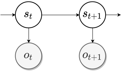
The diagram illustrates a sequential state transition model with two time steps (t and t+1). It depicts two state nodes (`S_t` and `S_{t+1}`) and two output nodes (`O_t` and `O_{t+1}`), connected by directional arrows indicating transitions. The structure suggests a temporal relationship between states and outputs, likely representing a system's behavior over discrete time intervals.
### Components/Axes
- **Nodes**:
- **State Nodes**:
- `S_t` (current state at time t)
- `S_{t+1}` (next state at time t+1)
- **Output Nodes**:
- `O_t` (output at time t)
- `O_{t+1}` (output at time t+1)
- **Arrows**:
- Horizontal arrows: `S_t → S_{t+1}` (state transition)
- Vertical arrows: `O_t → O_{t+1}` (output transition)
- **No legends, color coding, or numerical scales** are present.
### Detailed Analysis
- **State Transition**: The system evolves from `S_t` to `S_{t+1}` via a deterministic or stochastic process (not specified in the diagram).
- **Output Generation**: Outputs `O_t` and `O_{t+1}` are directly tied to their respective states, implying a functional relationship (e.g., `O_t = f(S_t)`).
- **Temporal Coupling**: The vertical alignment of `O_t` and `O_{t+1}` under their corresponding states emphasizes synchronization between state and output timelines.
### Key Observations
1. **Unidirectional Flow**: All transitions are one-way (no feedback loops or bidirectional arrows).
2. **Minimalist Design**: No additional annotations, labels, or contextual details are provided.
3. **Temporal Abstraction**: The use of `t` and `t+1` suggests a focus on incremental changes rather than absolute time.
### Interpretation
This diagram likely represents a **state machine** or **Markov process** where:
- **States** (`S_t`, `S_{t+1}`) encode the system's condition at discrete time steps.
- **Outputs** (`O_t`, `O_{t+1}`) are observable consequences of the system's state (e.g., sensor readings, actions).
- The absence of feedback loops implies a **sequential, non-recurrent** process, where future states depend only on the current state (Markov property).
The simplicity of the diagram highlights its role as a conceptual model, possibly for:
- **Control systems** (e.g., robotics, automation).
- **Signal processing** (e.g., time-series analysis).
- **Machine learning** (e.g., recurrent neural networks, though this diagram lacks feedback loops).
### Limitations
- **No Transition Rules**: The diagram does not specify how `S_t` determines `S_{t+1}` or `O_t` determines `O_{t+1}`.
- **No Probabilistic Weights**: If this is a probabilistic model (e.g., Markov chain), transition probabilities are omitted.
- **No Context**: The purpose of the states/outputs (e.g., "temperature," "action") is undefined.
This abstraction prioritizes structural clarity over implementation details, making it suitable for high-level system design or theoretical analysis.