## Diagram: CPU Instruction Processing Pipeline
### Overview
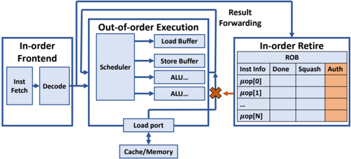
This diagram illustrates a CPU's instruction processing pipeline, highlighting in-order and out-of-order execution stages, memory interactions, and result retirement. The flow progresses from instruction fetch to execution and finally to result retirement, with explicit components for scheduling, buffering, and status tracking.
### Components/Axes
1. **In-order Frontend** (Left):
- **Inst Fetch**: Instruction fetch stage.
- **Decode**: Instruction decoding stage.
- Connected via arrows to the **Scheduler** in the out-of-order execution block.
2. **Out-of-order Execution** (Center):
- **Scheduler**: Central component managing instruction dispatch.
- **Load Buffer**: Handles load operations.
- **Store Buffer**: Manages store operations.
- **ALU...**: Arithmetic Logic Units (multiple instances implied).
- **Load Port**: Interface to memory/cache (labeled "Cache/Memory" at the bottom).
3. **In-order Retire** (Right):
- **ROB (Reorder Buffer)**: Tracks instruction status with columns:
- **Inst Info**: Instruction identifier (e.g., `μop[0]`, `μop[1]`, ..., `μop[N]`).
- **Done**: Completion status (empty in diagram).
- **Squash**: Invalidated instructions (empty in diagram).
- **Auth**: Authorization status (highlighted in orange).
4. **Result Forwarding**: Arrows connect the out-of-order execution block to the ROB, ensuring results are written back in program order.
### Detailed Analysis
- **Flow Direction**:
- Instructions flow left-to-right: Fetch → Decode → Scheduler → Execution → Retirement.
- Results are forwarded from the out-of-order execution block to the ROB for in-order retirement.
- **Key Elements**:
- **Load/Store Buffers**: Buffer memory operations to decouple execution from memory latency.
- **ALUs**: Represent computational units for arithmetic/logic operations.
- **ROB Columns**:
- `μop[N]`: Unique instruction identifiers (N implies variable-length instruction queue).
- **Auth Column**: Highlighted in orange, suggesting a security or validation mechanism (e.g., speculative execution checks).
### Key Observations
- **Pipeline Parallelism**: The scheduler dispatches instructions to multiple ALUs, enabling out-of-order execution.
- **Memory Hierarchy**: The Load Port directly interfaces with Cache/Memory, emphasizing memory access latency as a critical factor.
- **Auth Column Significance**: The orange highlight on the "Auth" column implies a security or validation step during retirement, possibly to prevent unauthorized or erroneous instructions from committing.
### Interpretation
This diagram represents a modern CPU's out-of-order execution engine, balancing performance and correctness. The **Auth column** in the ROB likely serves as a safeguard against speculative execution vulnerabilities (e.g., Meltdown/Spectre), ensuring only authorized instructions retire. The separation of in-order fetch/decode and out-of-order execution allows the CPU to exploit instruction-level parallelism while maintaining program-order semantics during retirement. The Load/Store Buffers and ALUs highlight the CPU's ability to overlap memory accesses and computations, reducing stalls. The absence of values in the ROB suggests this is a conceptual diagram, focusing on architectural components rather than performance metrics.