## Diagram: Out-of-Order Execution Pipeline
### Overview
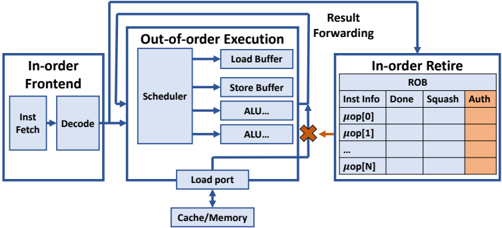
The image is a diagram illustrating the architecture of an out-of-order execution pipeline in a processor. It shows the flow of instructions through different stages, including the in-order frontend, out-of-order execution core, and in-order retire stage.
### Components/Axes
* **In-order Frontend:** This block is located on the left side of the diagram. It contains two sub-blocks:
* Inst Fetch: Instruction Fetch unit.
* Decode: Instruction Decode unit.
* **Out-of-order Execution:** This block is located in the center of the diagram. It contains the following sub-blocks:
* Scheduler
* Load Buffer
* Store Buffer
* ALU... (multiple Arithmetic Logic Units)
* Load port
* Cache/Memory
* **In-order Retire:** This block is located on the right side of the diagram. It contains a table labeled "ROB" (Re-Order Buffer) with the following columns:
* Inst Info
* Done
* Squash
* Auth (partially shaded in orange)
* Rows are labeled as:
* μop[0]
* μop[1]
* ...
* μop[N]
* **Arrows:** Arrows indicate the flow of instructions and data between the different stages.
* An arrow goes from "Inst Fetch" to "Decode".
* An arrow goes from "Decode" to "Scheduler".
* Arrows go from "Scheduler" to "Load Buffer", "Store Buffer", and "ALU...".
* An arrow goes from "Load port" to "Cache/Memory".
* An arrow goes from "Cache/Memory" back to "Load port".
* An arrow goes from "Scheduler" to "Load port".
* An arrow goes from "ALU..." to "In-order Retire" with a red "X" on the arrow.
* An arrow goes from "In-order Retire" to "Scheduler" labeled "Result Forwarding".
* An arrow goes from "Load Buffer" to "In-order Retire" labeled "Result Forwarding".
* An arrow goes from "Store Buffer" to "In-order Retire" labeled "Result Forwarding".
### Detailed Analysis or Content Details
The diagram illustrates the flow of instructions through a typical out-of-order execution pipeline. Instructions are fetched and decoded in the in-order frontend. The decoded instructions are then sent to the scheduler in the out-of-order execution core. The scheduler determines when instructions are ready to be executed based on data dependencies and resource availability. Instructions are then dispatched to the appropriate execution units (Load Buffer, Store Buffer, ALU). The results of the executed instructions are then forwarded to the in-order retire stage, where they are committed to the architectural state in the original program order. The ROB (Re-Order Buffer) is used to track the status of instructions and ensure that they are retired in the correct order.
### Key Observations
* The diagram highlights the key components of an out-of-order execution pipeline.
* The arrows clearly show the flow of instructions and data between the different stages.
* The ROB table illustrates how instructions are tracked and retired in order.
* The "Result Forwarding" path shows how results are fed back to the scheduler to reduce stalls.
### Interpretation
The diagram provides a high-level overview of the architecture of an out-of-order execution pipeline. It demonstrates how instructions can be executed out of order to improve performance, while still maintaining the correct program order. The use of a scheduler and ROB allows the processor to dynamically reorder instructions and execute them in parallel, maximizing resource utilization and minimizing stalls. The "Result Forwarding" path is a critical optimization that allows instructions to receive results directly from the execution units, without having to wait for them to be written to memory. The red "X" on the arrow from "ALU..." to "In-order Retire" indicates a potential hazard or conflict that needs to be resolved before the instruction can be retired.