## Diagram: Processor Pipeline Architecture
### Overview
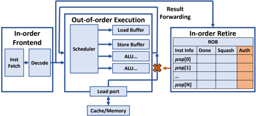
The image depicts a simplified block diagram of a processor pipeline, illustrating the flow of instructions through different stages: In-order Frontend, Out-of-order Execution, and In-order Retire. It highlights key components within each stage and the data flow between them. The diagram also shows a hazard condition (data dependency) represented by a red "X".
### Components/Axes
The diagram consists of three main blocks:
1. **In-order Frontend:** Contains "Inst Fetch" (Instruction Fetch) and "Decode" stages.
2. **Out-of-order Execution:** Contains "Scheduler", "Load Buffer", "Store Buffer", and two "ALU..." blocks. A "Load port" connects this block to "Cache/Memory".
3. **In-order Retire:** Contains a "ROB" (Reorder Buffer) table with columns labeled "Inst Info", "Done", "Squash", and "Auth".
Arrows indicate the flow of instructions between stages. A label "Result Forwarding" points to an arrow connecting the Out-of-order Execution block to the In-order Retire block.
### Content Details
The "In-order Frontend" block receives instructions and passes them to the "Out-of-order Execution" block. The "Out-of-order Execution" block contains a scheduler that manages the execution of instructions, load and store buffers for memory access, and multiple Arithmetic Logic Units (ALUs). The "Load port" connects the "Out-of-order Execution" block to the "Cache/Memory" for data retrieval.
The "In-order Retire" block contains a Reorder Buffer (ROB) table. The table has rows labeled "μop[0]", "μop[1]", "...", "μop[N]", representing micro-operations. The columns represent the status of each micro-operation:
* **Inst Info:** Instruction Information
* **Done:** Indicates if the instruction is completed.
* **Squash:** Indicates if the instruction has been squashed (cancelled).
* **Auth:** (Highlighted in orange) Indicates if the instruction is authorized for retirement.
A red "X" symbol indicates a hazard (data dependency) between the "Out-of-order Execution" block and the "In-order Retire" block. This suggests that an instruction in the execution stage is waiting for a result from a previous instruction that has not yet completed.
### Key Observations
* The pipeline is divided into three distinct stages: In-order Frontend, Out-of-order Execution, and In-order Retire.
* The Out-of-order Execution stage allows for parallel execution of instructions, potentially improving performance.
* The In-order Retire stage ensures that instructions are committed in the original program order, maintaining program correctness.
* The presence of a hazard (red "X") indicates a potential performance bottleneck.
* The ROB table provides a mechanism for tracking the status of instructions and handling exceptions.
### Interpretation
This diagram illustrates a common processor pipeline architecture used in modern CPUs. The separation of the pipeline into in-order and out-of-order stages allows for a balance between performance and correctness. The out-of-order execution stage exploits instruction-level parallelism to improve performance, while the in-order retire stage ensures that the program's semantics are preserved.
The hazard condition highlighted in the diagram is a common challenge in pipeline design. It occurs when an instruction depends on the result of a previous instruction that has not yet completed. Techniques like result forwarding (shown in the diagram) can be used to mitigate the impact of hazards.
The ROB table is a crucial component of the in-order retire stage. It allows the processor to track the status of instructions and handle exceptions or mispredictions. The "Auth" column indicates that an instruction has been verified and is ready to be committed to the architectural state. The diagram provides a high-level overview of the key components and data flow in a processor pipeline, demonstrating how these elements work together to execute instructions efficiently and correctly.