# Technical Diagram Analysis
## Diagram Overview
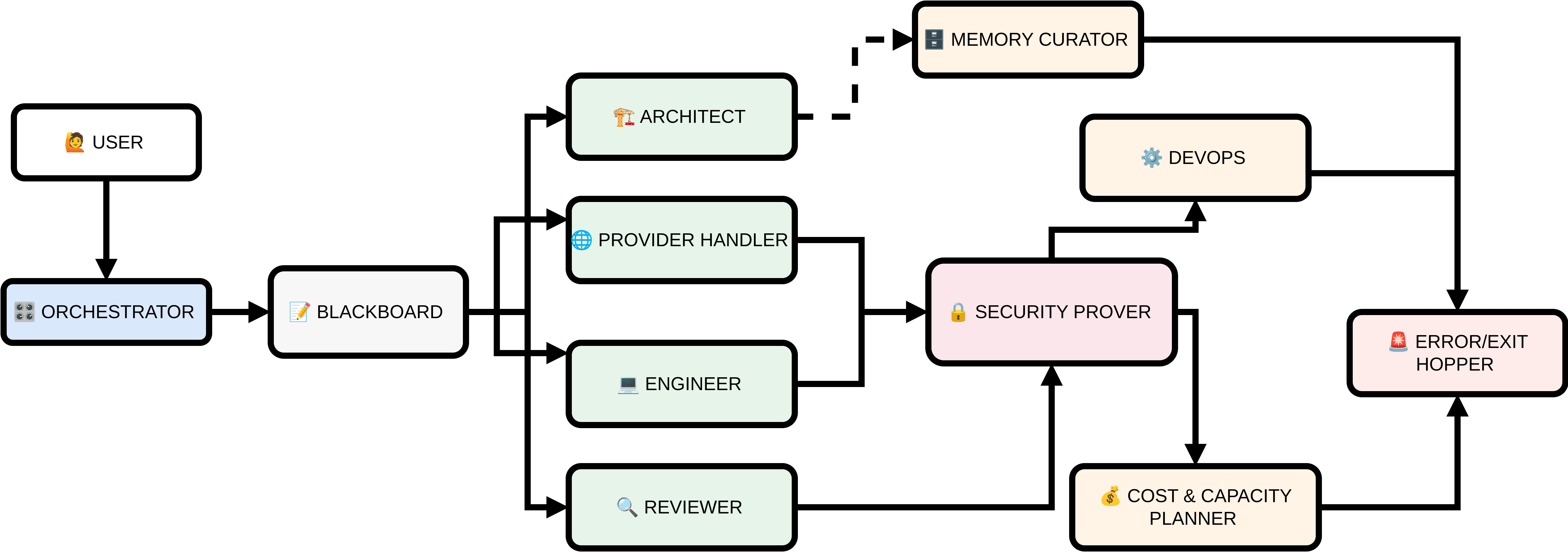
This is a **component interaction flowchart** depicting a system architecture with multiple interconnected roles and processes. The diagram uses color-coded boxes to represent different components, with arrows indicating data flow or control relationships.
---
## Key Components & Flow
### 1. User Interaction
- **USER** (👤)
- Input source for the system
- Directly connected to **ORCHESTRATOR**
### 2. Core Processing
- **ORCHESTRATOR** (🎛️)
- Central control unit
- Outputs to **BLACKBOARD**
- **BLACKBOARD** (📝)
- Intermediate processing node
- Branches to four parallel paths:
1. **ARCHITECT** (🏗️)
- Receives from BLACKBOARD
- Dashed connection to **MEMORY CURATOR** (💾)
2. **PROVIDER HANDLER** (🌐)
- Receives from BLACKBOARD
- Connects to **SECURITY PROVER** (🔐)
3. **ENGINEER** (💻)
- Receives from BLACKBOARD
- Connects to **SECURITY PROVER**
4. **REVIEWER** (🔍)
- Receives from BLACKBOARD
- Connects to **SECURITY PROVER**
### 3. Security & Validation
- **SECURITY PROVER** (🔐)
- Central validation node
- Receives from:
- PROVIDER HANDLER
- ENGINEER
- REVIEWER
- Outputs to:
- **COST & CAPACITY PLANNER** (💰)
- **DEVOPS** (⚙️)
- **ERROR/EXIT HOPPER** (🚨)
### 4. Resource Management
- **COST & CAPACITY PLANNER** (💰)
- Receives from SECURITY PROVER
- Outputs to ERROR/EXIT HOPPER
- **DEVOPS** (⚙️)
- Receives from SECURITY PROVER
- Outputs to ERROR/EXIT HOPPER
### 5. Error Handling
- **ERROR/EXIT HOPPER** (🚨)
- Final error-handling node
- Receives from:
- SECURITY PROVER
- COST & CAPACITY PLANNER
- DEVOPS
- Dashed connection to **MEMORY CURATOR**
### 6. Memory Management
- **MEMORY CURATOR** (💾)
- Receives from:
- ARCHITECT (dashed connection)
- ERROR/EXIT HOPPER
---
## Color Coding & Legend
- **Light Blue Boxes**: Core system components (ORCHESTRATOR, BLACKBOARD)
- **Light Green Boxes**: Role-based components (ARCHITECT, PROVIDER HANDLER, ENGINEER, REVIEWER)
- **Light Pink Boxes**: Process/validation components (SECURITY PROVER, COST & CAPACITY PLANNER, DEVOPS, ERROR/EXIT HOPPER)
- **Light Yellow Box**: Memory management (MEMORY CURATOR)
---
## Flow Analysis
1. **User → ORCHESTRATOR → BLACKBOARD**
Initial input processing through central control.
2. **Parallel Processing Paths**
BLACKBOARD distributes work to four specialized roles:
- Architectural design (ARCHITECT)
- Provider management (PROVIDER HANDLER)
- Engineering implementation (ENGINEER)
- Quality assurance (REVIEWER)
3. **Convergence at SECURITY PROVER**
All role outputs must pass security validation before proceeding.
4. **Divergent Outcomes**
SECURITY PROVER routes to:
- Resource planning (COST & CAPACITY PLANNER)
- Deployment automation (DEVOPS)
- Error handling (ERROR/EXIT HOPPER)
5. **Memory Integration**
ARCHITECT and ERROR/EXIT HOPPER have optional memory interactions.
---
## Critical Observations
1. **Security as a Bottleneck**
All non-memory paths must pass through SECURITY PROVER before proceeding.
2. **Error Handling Redundancy**
Multiple components feed into ERROR/EXIT HOPPER, suggesting robust failure management.
3. **Memory as Secondary System**
MEMORY CURATOR has only two connections, indicating limited integration.
4. **Dashed Connections**
Indicate optional or asynchronous interactions (ARCHITECT → MEMORY CURATOR).
---
## Missing Elements
- No explicit data tables or numerical values present
- No temporal or quantitative metrics shown
- No explicit error recovery paths beyond ERROR/EXIT HOPPER
---
## Summary
This diagram represents a **security-centric system architecture** with:
- User-driven input
- Parallel processing paths
- Centralized security validation
- Multi-stage error handling
- Memory integration points
The flowchart emphasizes security validation as a critical control point in the system workflow.