## Diagram: Graph Theory Network Structure
### Overview
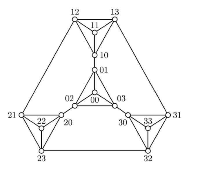
The image displays a symmetric, planar graph consisting of 16 nodes arranged in a recursive, triangular pattern. The structure is composed of four distinct clusters: a top cluster, a left cluster, a right cluster, and a central cluster. The nodes are labeled with two-digit identifiers, likely representing a coordinate or indexing system. The graph exhibits rotational symmetry and appears to be a representation of a specific mathematical graph, such as a Sierpinski graph or a variation of a Tower of Hanoi graph.
### Components/Axes
* **Nodes:** 16 circular nodes, each labeled with a two-digit number.
* **Edges:** Straight lines connecting the nodes, defining the network topology.
* **Labeling System:** The labels appear to be base-4 or coordinate-based, grouped by cluster:
* **Top Cluster:** 12, 13, 11, 10
* **Left Cluster:** 21, 22, 20, 23
* **Right Cluster:** 31, 33, 30, 32
* **Center Cluster:** 01, 00, 02, 03
### Detailed Analysis
#### Cluster Breakdown and Connectivity
The graph is highly interconnected, with specific nodes acting as bridges between the clusters.
* **Top Cluster (1x series):**
* **Nodes:** 12 (top-left), 13 (top-right), 11 (top-center), 10 (bottom-center of cluster).
* **Connections:** 12 connects to 13, 11, and 21. 13 connects to 12, 11, and 31. 11 connects to 12, 13, and 10. 10 connects to 11 and 01.
* **Left Cluster (2x series):**
* **Nodes:** 21 (far-left), 23 (bottom-left), 22 (inner), 20 (right-side of cluster).
* **Connections:** 21 connects to 22, 23, and 12. 23 connects to 22, 21, and 32. 22 connects to 20, 21, and 23. 20 connects to 22 and 02.
* **Right Cluster (3x series):**
* **Nodes:** 31 (far-right), 32 (bottom-right), 33 (inner), 30 (left-side of cluster).
* **Connections:** 31 connects to 33, 32, and 13. 32 connects to 33, 31, and 23. 33 connects to 30, 31, and 32. 30 connects to 33 and 03.
* **Center Cluster (0x series):**
* **Nodes:** 01 (top), 02 (left), 03 (right), 00 (center).
* **Connections:** 01 connects to 10, 02, 03, and 00. 02 connects to 20, 01, 03, and 00. 03 connects to 30, 01, 02, and 00. 00 connects to 01, 02, and 03.
### Key Observations
* **Symmetry:** The graph is rotationally symmetric. If rotated 120 degrees, the structure maps onto itself.
* **Outer Boundary:** There is a large outer triangle formed by the connections between 12-21, 23-32, and 31-13.
* **Bridge Nodes:** The nodes 10, 20, and 30 act as the primary "gateways" connecting the outer clusters to the central cluster.
* **Degree Distribution:** The nodes have varying degrees of connectivity. For example, node 01, 02, and 03 have a degree of 4 (connecting to the center and their respective outer clusters), while nodes 10, 20, and 30 have a degree of 2 (connecting only to their cluster and the center).
### Interpretation
This diagram represents a **Sierpinski graph** of order 2 (or a similar recursive graph structure). These graphs are often used in computer science and mathematics to model the state space of the Tower of Hanoi puzzle or to study fractal geometry.
The labeling system (00-33) is likely a positional notation where the first digit indicates the "branch" or "cluster" (0=center, 1=top, 2=left, 3=right) and the second digit indicates the specific node within that cluster. The structure demonstrates how a complex, recursive system can be broken down into self-similar sub-components, where the central cluster (0x) acts as the hub connecting the three outer branches. The "bridge" nodes (10, 20, 30) are critical bottlenecks in the network, as all traffic between the outer clusters and the center must pass through them.