## Diagram: Scene Representation and Object Attributes
### Overview
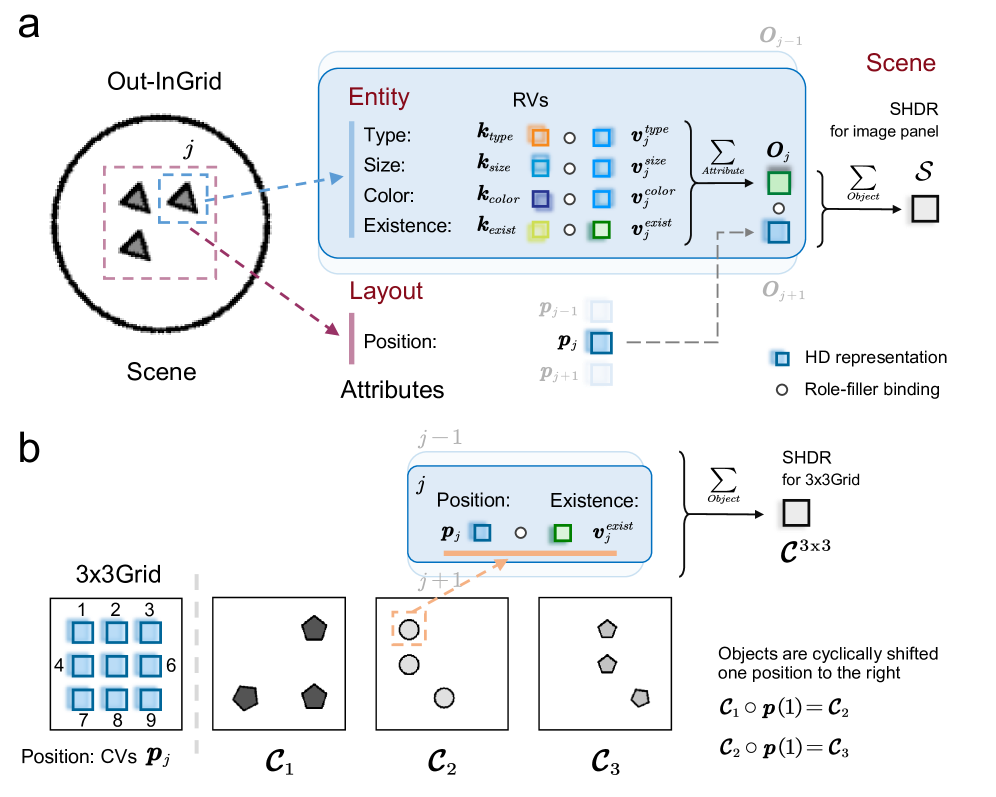
The image presents a diagram illustrating how scenes are represented and how object attributes are handled within a system, likely related to computer vision or scene understanding. It shows the relationship between "Out-InGrid" scenes, entity attributes, and their representation using Random Variables (RVs) and High-Dimensional (HD) representations. The diagram is split into two parts, (a) and (b), each showing a different aspect of the representation.
### Components/Axes
**Part a:**
* **Out-InGrid Scene:** A circular area labeled "Scene" containing a smaller dashed square labeled "j" with three dark triangles inside.
* **Entity:** A rounded rectangle labeled "Entity" with the following attributes:
* Type: Associated with `k_type` (orange square) and `v_j^{type}` (orange circle).
* Size: Associated with `k_size` (light blue square) and `v_j^{size}` (light blue circle).
* Color: Associated with `k_color` (dark blue square) and `v_j^{color}` (dark blue circle).
* Existence: Associated with `k_exist` (light green square) and `v_j^{exist}` (light green circle).
* **RVs:** Column of squares and circles representing Random Variables.
* **Layout:** A vertical bar labeled "Position" associated with `p_j` (light blue square).
* **Attributes:** General label for Position.
* **Scene:** A box labeled "Scene" with "SHDR for image panel" above it, leading to a square box labeled "S".
* **Legend:**
* HD representation (light blue square)
* Role-filler binding (white circle)
**Part b:**
* **3x3Grid:** A 3x3 grid with cells numbered 1 to 9, with cells 1, 2, 3, 4, 6, 7, 8, and 9 filled with light blue squares. Labeled "Position: CVs `p_j`".
* **C1, C2, C3:** Three boxes containing different arrangements of gray pentagons and circles.
* **Position:** Associated with `p_j` (light blue square) and an orange circle.
* **Existence:** Associated with `v_j^{exist}` (light green square) and a white circle.
* **SHDR for 3x3Grid:** Text above a square box labeled "C^{3x3}".
* **Equations:**
* `C_1 o p(1) = C_2`
* `C_2 o p(1) = C_3`
### Detailed Analysis
**Part a:**
* The "Out-InGrid" scene is linked to the "Entity" attributes via dashed lines.
* The attributes (Type, Size, Color, Existence) are represented by both `k` values (squares) and `v_j` values (circles).
* The `v_j` values are summed up (`Σ Attribute`) to produce `O_j` (light green square).
* `O_j` is then summed up (`Σ Object`) to produce "S" (white square), which represents the SHDR for the image panel.
* `p_j` (light blue square) is connected to `O_j+1` via a dashed line.
**Part b:**
* The 3x3 grid represents possible positions.
* `C1`, `C2`, and `C3` show different configurations of objects.
* The objects are cyclically shifted one position to the right.
* The equations `C_1 o p(1) = C_2` and `C_2 o p(1) = C_3` describe this cyclic shift.
* The objects in `C1`, `C2`, and `C3` are summed up (`Σ Object`) to produce "C^{3x3}" (white square), which represents the SHDR for the 3x3 grid.
### Key Observations
* The diagram uses both squares (HD representation) and circles (Role-filler binding) to represent different aspects of the data.
* The diagram shows a hierarchical structure, starting from individual entities and building up to a complete scene representation.
* Part (b) illustrates a specific example of how objects are shifted within a grid.
### Interpretation
The diagram illustrates a system for representing scenes and objects within those scenes. The "Out-InGrid" likely refers to a method for focusing on specific regions within a larger scene. The "Entity" section details how objects are characterized by attributes like type, size, color, and existence, each represented by a `k` value (likely a constant or known parameter) and a `v_j` value (likely a variable or learned parameter). These attributes are then combined to form a scene representation (SHDR).
Part (b) provides a concrete example of how object positions are handled within a 3x3 grid. The cyclic shift operation suggests a mechanism for exploring different spatial arrangements of objects. The equations `C_1 o p(1) = C_2` and `C_2 o p(1) = C_3` formalize this shift, indicating a mathematical operation `o` that applies a position shift `p(1)` to the object configuration.
Overall, the diagram describes a system that combines object attributes and spatial relationships to create a comprehensive scene representation. This representation could be used for various tasks, such as object recognition, scene understanding, or robotic navigation.