## Diagram: Memory Bank Power Management
### Overview
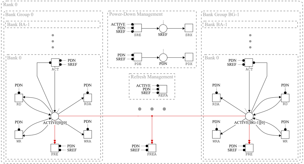
The image is a diagram illustrating the power management and refresh mechanisms within a memory bank architecture. It depicts the flow of power-down (PDN) and self-refresh (SREF) signals across different components of the memory system, including bank groups, banks, and individual memory cells. The diagram highlights the interaction between active states, refresh operations, and power-down sequences.
### Components/Axes
* **Hierarchical Structure:** The diagram shows a hierarchical memory organization, with levels including "Rank 0", "Bank Group 0", "Bank BA-1", and "Bank 0". A similar structure exists for "Bank Group BG-1".
* **Power-Down Management:** This section illustrates the sequence of states involved in power-down, including SRE, SREF, and SRX, as well as PDE, PDN, and PDX.
* **Refresh Management:** This section shows the REFA state, indicating a refresh operation.
* **Active States:** The diagram features "ACTIVE[0][0]" and "ACTIVE[BG-1][0]" states, representing the active state of memory cells.
* **Memory Operations:** The diagram includes nodes representing memory operations such as RD (Read), WR (Write), RDA (Read with Activate), and WRA (Write with Activate). PRE (Precharge) and PREA (Precharge All).
* **Signal Indicators:** The diagram uses dotted lines to indicate PDN and SREF signals.
### Detailed Analysis
* **Bank Group 0:**
* **Rank 0:** Top level of the hierarchy.
* **Bank Group 0:** Second level of the hierarchy.
* **Bank BA-1:** Third level of the hierarchy.
* **Bank 0:** Contains the core memory operations and active state.
* **ACT:** Connected to PDN and SREF signals.
* **ACTIVE[0][0]:** Central node connected to RD, WR, RDA, WRA, and PRE.
* **RD:** Connected to PDN signal.
* **WR:** Connected to PDN signal.
* **RDA:** Connected to PDN signal.
* **WRA:** Connected to PDN signal.
* **PRE:** Connected to PDN and SREF signals.
* **Bank Group BG-1:**
* **Rank 0:** Top level of the hierarchy.
* **Bank Group BG-1:** Second level of the hierarchy.
* **Bank BA-1:** Third level of the hierarchy.
* **Bank 0:** Contains the core memory operations and active state.
* **ACT:** Connected to PDN and SREF signals.
* **ACTIVE[BG-1][0]:** Central node connected to RD, WR, RDA, WRA, and PRE.
* **RD:** Connected to PDN signal.
* **WR:** Connected to PDN signal.
* **RDA:** Connected to PDN signal.
* **WRA:** Connected to PDN signal.
* **PRE:** Connected to PDN and SREF signals.
* **Power-Down Management:**
* **ACTIVE:** Connected to PDN and SREF signals.
* **SRE:** State in the power-down sequence.
* **SREF:** State in the power-down sequence.
* **SRX:** State in the power-down sequence.
* **PDE:** State in the power-down sequence.
* **PDN:** State in the power-down sequence.
* **PDX:** State in the power-down sequence.
* **Refresh Management:**
* **ACTIVE:** Connected to PDN and SREF signals.
* **REFA:** State indicating a refresh operation.
* **Interconnections:**
* The "ACTIVE[0][0]" state is connected to "PREA" via a red line, indicating a direct transition.
* The "ACTIVE[BG-1][0]" state is connected to "PREA" via a red line, indicating a direct transition.
### Key Observations
* The diagram illustrates the flow of control signals (PDN, SREF) through different states and operations within the memory bank.
* The "ACTIVE" states are central nodes, connecting to various memory operations and power management sequences.
* The red lines highlight a specific transition from the active state to the precharge all state.
* The diagram shows a mirrored structure for Bank Group 0 and Bank Group BG-1, suggesting a similar architecture and operation.
### Interpretation
The diagram provides a high-level overview of the power management and refresh mechanisms in a memory bank. It demonstrates how the memory system transitions between active, power-down, and refresh states. The hierarchical structure indicates a modular design, where individual banks are grouped into larger units. The red lines connecting the active states to the precharge all state suggest a critical path or a common operation performed during memory management. The diagram is useful for understanding the control flow and state transitions within the memory system, which is essential for optimizing power consumption and performance.