## Diagram: Memory Bank Power and Refresh Management
### Overview
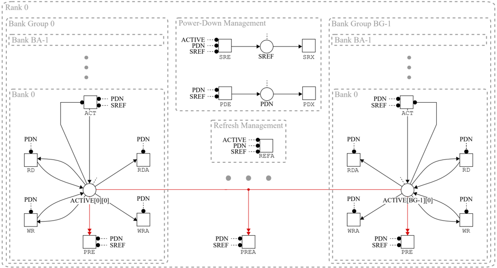
The image depicts a diagram illustrating the power-down and refresh management architecture for two memory bank groups (BG-0 and BG-1), each containing multiple banks. The diagram focuses on the signal flow and control mechanisms related to power distribution and data retention during various operational states. The diagram is divided into two main sections representing the two bank groups, with a central section detailing the power-down and refresh management logic.
### Components/Axes
The diagram includes the following key components:
* **Bank Groups:** BG-0 (left side) and BG-1 (right side). Each group contains multiple banks (Bank 0, Bank BA-1).
* **Banks:** Represented by rectangles labeled "PDN" and containing internal blocks labeled "ACT", "RD", "RDA", "WR", "WRA", and "PRE".
* **Power-Down Management:** A central section with blocks labeled "ACTIVE", "PDN", "SREF", "SRX", "PDE", "PDX".
* **Refresh Management:** A central section with blocks labeled "ACTIVE", "PDN", "SREF", "REFA".
* **Signals:** Represented by arrows connecting the components, labeled with abbreviations like "SREF", "SRX", "PDE", "PDX", "REFA", "PREA".
* **Ellipses:** Represent state machines or control logic within the power-down and refresh management sections.
* **Rank 0:** Label at the top-left indicating the rank of the memory.
* **Bank Group 0:** Label indicating the first bank group.
* **Bank BA-1:** Label indicating a specific bank within the bank groups.
* **Bank 0:** Label indicating a specific bank within the bank groups.
### Detailed Analysis / Content Details
**Bank Group 0 (Left Side):**
* **Top Level:** A "PDN" block labeled "SREF" connects to an "ACT" block.
* **Middle Level:** The "ACT" block feeds into two "PDN" blocks labeled "RD" and "RDA".
* **Bottom Level:** "RD" and "RDA" connect to a "PDN" block labeled "ACTIVE[0][0]". This block then connects to "WR" and "WRA" blocks.
* **Bottom-most Level:** "WR" and "WRA" connect to "PDN" blocks labeled "SREF" and "PRE".
**Bank Group 1 (Right Side):**
* **Top Level:** A "PDN" block labeled "SREF" connects to an "ACT" block.
* **Middle Level:** The "ACT" block feeds into two "PDN" blocks labeled "RD" and "RDA".
* **Bottom Level:** "RD" and "RDA" connect to a "PDN" block labeled "ACTIVE[BG-1][0]". This block then connects to "WR" and "WRA" blocks.
* **Bottom-most Level:** "WR" and "WRA" connect to "PDN" blocks labeled "SREF" and "PRE".
**Power-Down Management (Center-Top):**
* An "ACTIVE" block labeled "PDN" and "SREF" connects to an ellipse labeled "SRE".
* "SRE" connects to an ellipse labeled "SREF".
* "SREF" connects to an ellipse labeled "SRX".
**Refresh Management (Center-Bottom):**
* An "ACTIVE" block labeled "PDN" and "SREF" connects to an ellipse labeled "REFA".
* "REFA" connects to a "PDN" block labeled "SREF".
* A "PDN" block labeled "SREF" connects to an ellipse labeled "PDE".
* "PDE" connects to an ellipse labeled "PDX".
**Signal Connections:**
* A dotted line connects the "PRE" block in Bank Group 0 to a "PDN" block labeled "PREA" in the Refresh Management section.
* A dotted line connects the "PRE" block in Bank Group 1 to a "PDN" block labeled "PREA" in the Refresh Management section.
### Key Observations
* The diagram shows a symmetrical structure for both bank groups, suggesting a consistent power and refresh management scheme.
* The "ACTIVE" blocks appear to be central control points for both power-down and refresh operations.
* The use of ellipses suggests state machines or control logic that govern the transitions between different power and refresh states.
* The dotted lines indicate a connection between the banks and the refresh management logic, likely for initiating refresh cycles.
* The labels "PDN" and "SREF" appear frequently, indicating their importance in the power and refresh control scheme.
### Interpretation
The diagram illustrates a sophisticated power and refresh management system for memory banks. The system aims to optimize power consumption by selectively powering down inactive banks while ensuring data retention through periodic refresh cycles. The "ACTIVE" blocks likely represent the active state of a bank, while the "PDN" blocks indicate power-down states. The ellipses represent the control logic that manages the transitions between these states based on various signals and conditions.
The symmetrical structure of the bank groups suggests that the power and refresh management scheme is applied uniformly across all banks. The dotted lines connecting the banks to the refresh management logic indicate that the refresh cycles are initiated based on the activity or inactivity of the banks. The diagram provides a high-level overview of the system architecture and does not delve into the specific details of the control algorithms or timing parameters.
The diagram is likely intended for engineers involved in the design and verification of memory systems, providing a visual representation of the power and refresh management architecture. It highlights the key components and signal flows, enabling a better understanding of the system's functionality and behavior. The use of abbreviations and technical terms suggests that the audience is familiar with memory system terminology. The diagram does not contain any numerical data or performance metrics, focusing instead on the structural aspects of the system.