TECHNICAL ASSET FINGERPRINT
8a3eace8e535b035753a4eaf
Click to view fullscreen
Press ESC or click to close
FOUND IN PAPERS
EXPERT: healer-alpha-free VERSION 1
RUNTIME: free/openrouter/healer-alpha
INTEL_VERIFIED
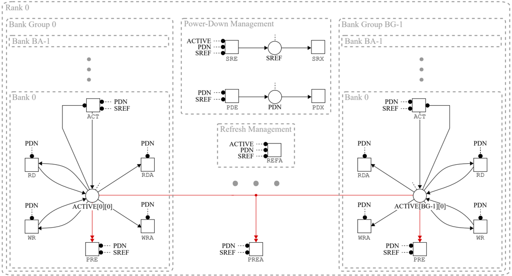
## Technical Diagram: Memory Bank State and Management Architecture
### Overview
This image is a technical state diagram illustrating the operational states, transitions, and management logic for a multi-bank memory system (likely DRAM). It details the relationships between active operations, power-down modes, and refresh commands across multiple bank groups within a single rank. The diagram uses a combination of state boxes, directional arrows, and control signals to map the system's behavior.
### Components/Axes
The diagram is segmented into four primary regions:
1. **Header Label:** "Rank 0" is centered at the very top.
2. **Left Region - Bank Group 0:** A large dashed box containing:
* A sub-box for "Bank BA-1" with ellipsis (three vertical dots) indicating continuation.
* A sub-box for "Bank 0" containing the core state machine.
3. **Right Region - Bank Group BG-1:** A large dashed box mirroring the left, containing:
* A sub-box for "Bank BA-1" with ellipsis.
* A sub-box for "Bank 0" containing a mirrored state machine.
4. **Central Management Region:** Located between the two bank groups, containing two dashed boxes:
* **Top: "Power-Down Management"**
* **Bottom: "Refresh Management"**
**Key Components & Labels:**
* **State Boxes:** Represented as squares or circles. Key states include:
* `ACT` (Active)
* `RD` (Read), `RDA` (Read with Auto-precharge)
* `WR` (Write), `WRA` (Write with Auto-precharge)
* `PRE` (Precharge), `PREA` (Precharge All)
* `SRE` (Self-Refresh Entry), `SREF` (Self-Refresh), `SRX` (Self-Refresh Exit)
* `PDE` (Power-Down Entry), `PDN` (Power-Down), `PDX` (Power-Down Exit)
* `REFA` (Refresh All)
* **Control Signals:** Indicated by dashed lines with black dots, feeding into state boxes. The primary signals are:
* `ACTIVE`
* `PDN` (Power-Down)
* `SREF` (Self-Refresh)
* **Central Nodes:** Two circular nodes labeled `ACTIVE[0][0]` (left) and `ACTIVE[BG-1][0]` (right) act as hubs for their respective bank groups.
* **Flow Lines:** Solid black arrows show standard state transitions. Solid **red arrows** indicate a specific, shared transition path from the central `ACTIVE` nodes to the `PREA` state.
### Detailed Analysis
**1. Bank Group 0 & BG-1 State Machines (Left & Right Regions):**
* **Structure:** Both bank groups have identical, mirrored internal structures for their "Bank 0".
* **Central Hub:** The `ACTIVE[0][0]` (left) and `ACTIVE[BG-1][0]` (right) nodes are the central points from which all active commands originate.
* **Transitions from ACTIVE Hub:**
* To `RD` and `WR` states (standard read/write).
* To `RDA` and `WRA` states (read/write with auto-precharge).
* To the `PRE` state (individual bank precharge).
* **A red arrow** points from each `ACTIVE` hub down to a shared `PREA` (Precharge All) state located in the central region.
* **Transitions to ACTIVE Hub:** Arrows flow from `RD`, `WR`, `RDA`, and `WRA` back to the `ACTIVE` hub, indicating these are temporary states within an active cycle.
* **Power-Down Inputs:** The `PDN` and `SREF` control signals are shown as inputs to the `ACT`, `RD`, `WR`, `RDA`, `WRA`, and `PRE` states, indicating these states can be interrupted or influenced by power-down requests.
**2. Power-Down Management (Top-Center):**
* This box defines two distinct power-down sequences:
* **Self-Refresh Path:** `SRE` (Entry) -> `SREF` (State) -> `SRX` (Exit). Triggered by `ACTIVE`, `PDN`, and `SREF` signals.
* **Standard Power-Down Path:** `PDE` (Entry) -> `PDN` (State) -> `PDX` (Exit). Triggered by `PDN` and `SREF` signals.
**3. Refresh Management (Bottom-Center):**
* Contains a single state box `REFA` (Refresh All).
* It is triggered by the `ACTIVE`, `PDN`, and `SREF` control signals.
**4. Shared Precharge All (`PREA`) State:**
* Located at the bottom center, this state is the target of the **red arrows** from both bank groups' `ACTIVE` hubs.
* It is also influenced by the `PDN` and `SREF` control signals.
### Key Observations
1. **Symmetry and Scalability:** The design is highly symmetrical, with Bank Group 0 and Bank Group BG-1 being mirror images. The ellipsis under "Bank BA-1" in both groups implies the architecture scales to support multiple banks per group.
2. **Centralized vs. Distributed Control:** While individual bank operations (RD, WR, PRE) are managed within each bank group, critical system-wide operations like `PREA` (Precharge All), `REFA` (Refresh All), and the power-down sequences are centralized.
3. **Critical Path Highlighting:** The use of **red lines** specifically for the path from any active bank to the `PREA` state emphasizes this as a high-priority or broadcast command that affects all banks simultaneously.
4. **Power-Aware Design:** The pervasive presence of `PDN` and `SREF` signals as inputs to nearly every state underscores that power management is a first-class concern integrated into all operational modes, not just a separate state.
### Interpretation
This diagram models the complex control logic for a modern DRAM memory subsystem. It demonstrates how a memory controller must manage concurrent operations across multiple banks while adhering to strict power and refresh constraints.
* **What it demonstrates:** The system is designed for parallelism (multiple banks can be active) but requires careful coordination. The `PREA` and `REFA` states act as synchronization points that momentarily halt normal operation across all banks to perform maintenance (precharge for readiness, refresh for data integrity).
* **Relationships:** The bank groups operate semi-independently for reads, writes, and precharges, but are slaved to the central management logic for power-down entry/exit and refresh cycles. The control signals (`ACTIVE`, `PDN`, `SREF`) act as global interrupts that can steer any bank's state machine into a management routine.
* **Notable Design Choice:** The integration of power-down signals (`PDN`, `SREF`) into the input of the `ACT`, `RD`, and `WR` states is significant. It suggests the hardware can initiate a power-down sequence *during* an active command, implying sophisticated power gating that doesn't wait for a natural idle period. This points to an aggressive power-saving strategy. The clear separation between Self-Refresh (a deeper sleep state for retention) and standard Power-Down (likely a lighter sleep for quick wake-up) further highlights a nuanced power management hierarchy.
DECODING INTELLIGENCE...