## Diagram: Banking System Architecture with Power-Down and Refresh Management
### Overview
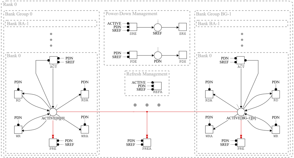
The diagram illustrates a distributed banking system architecture with two bank groups (Bank Group 0 and Bank Group BG-1), each containing sub-banks (e.g., Bank BA-1, Bank 0). It emphasizes power-down management, refresh management, and inter-bank communication. Arrows indicate data flow, control signals, and synchronization between components.
### Components/Axes
#### Key Labels and Elements:
1. **Bank Groups**:
- **Bank Group 0**: Contains Bank BA-1 and Bank 0.
- **Bank Group BG-1**: Contains Bank BA-1 and Bank 0.
2. **Power-Down Management**:
- **ACTIVE** → **PDN** → **SREF** → **SRX** (left-to-right flow).
- **PDN** → **PDE** (dashed line).
3. **Refresh Management**:
- **ACTIVE** → **PDN** → **SREF** → **REFEA** (dashed box).
4. **Bank Components**:
- **PDN** (Power-Down Node), **ACT** (Active Transaction), **SREF** (Refresh Signal), **SRX** (Refresh Acknowledge), **RDA** (Read Data), **WR** (Write), **WRA** (Write Acknowledge).
5. **Connectors**:
- Red bidirectional line between Bank Group 0 and Bank Group BG-1, labeled with **ACTIVE[0][0]** and **ACTIVE[BG-1][0]**.
#### Spatial Grounding:
- **Top-Left**: Bank Group 0 (Bank BA-1, Bank 0).
- **Center**: Power-Down Management and Refresh Management blocks.
- **Top-Right**: Bank Group BG-1 (Bank BA-1, Bank 0).
- **Bottom**: Red line connecting Bank Groups 0 and BG-1.
### Detailed Analysis
#### Bank Group 0 (Left Side):
- **Bank 0**:
- **ACT** connects to **PDN**, which links to **SREF** and **RDA**.
- **PDN** also connects to **WR** and **WRA**.
- **Bank BA-1**:
- Similar structure to Bank 0, with **ACT**, **PDN**, **SREF**, **RDA**, **WR**, and **WRA**.
#### Power-Down Management (Center):
- **ACTIVE** initiates a sequence:
- **PDN** (Power-Down Node) → **SREF** (Refresh Signal) → **SRX** (Refresh Acknowledge).
- Dashed line from **PDN** to **PDE** (Power-Down Execution).
#### Refresh Management (Center):
- **ACTIVE** triggers:
- **PDN** → **SREF** → **REFEA** (Refresh Execution Acknowledge).
#### Bank Group BG-1 (Right Side):
- Mirrors Bank Group 0, with identical component connections.
#### Critical Connections:
- Red bidirectional line between Bank Groups 0 and BG-1:
- **ACTIVE[0][0]** (Bank Group 0) ↔ **ACTIVE[BG-1][0]** (Bank Group BG-1).
- **PDN** and **SREF** signals propagate across both groups.
### Key Observations
1. **Symmetry**: Both bank groups have identical component structures, suggesting redundancy or load balancing.
2. **Power-Down Flow**: The sequence **ACTIVE → PDN → SREF → SRX** indicates a hierarchical shutdown process.
3. **Refresh Synchronization**: The **REFEA** component in Refresh Management ensures coordination during system refreshes.
4. **Bidirectional Communication**: The red line implies real-time synchronization between Bank Groups 0 and BG-1.
### Interpretation
This diagram represents a fault-tolerant banking system designed for high availability. The **Power-Down Management** ensures orderly shutdowns to prevent data corruption, while **Refresh Management** maintains data integrity during updates. The bidirectional red line between bank groups suggests a distributed consensus mechanism, enabling the system to handle failures or load spikes by redistributing tasks. The use of **ACTIVE** as a trigger for both power-down and refresh processes highlights its role as a central control signal.
The architecture prioritizes redundancy (dual bank groups) and synchronization, critical for financial systems requiring uninterrupted service. The absence of numerical data implies this is a conceptual or high-level design, focusing on component interactions rather than performance metrics.