## Diagram: Memory and Chunk Processing
### Overview
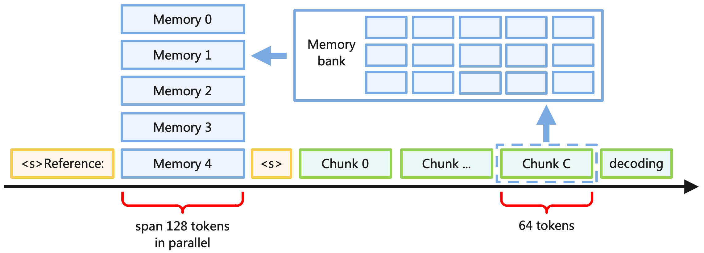
The image is a diagram illustrating the flow of data and processing steps involving memory and data chunks. It shows how data is accessed from memory, processed into chunks, and then decoded. The diagram includes memory blocks, chunk representations, and annotations indicating the span of tokens processed in parallel.
### Components/Axes
* **Memory Blocks:** Five blue rectangular blocks labeled "Memory 0", "Memory 1", "Memory 2", "Memory 3", and "Memory 4". These are stacked vertically on the left side of the diagram.
* **Memory Bank:** A larger blue rectangular block containing 12 smaller rectangles, representing a memory bank. It is located to the right of the memory blocks.
* **Chunks:** Green rectangular blocks labeled "Chunk 0", "Chunk ...", "Chunk C", and "decoding". These represent data chunks being processed.
* **Reference Blocks:** Yellow rectangular blocks labeled "<s\>Reference:" and "<\s\>".
* **Timeline:** A horizontal black arrow indicating the flow of processing from left to right.
* **Annotations:** Red brackets with text indicating "span 128 tokens in parallel" and "64 tokens".
* **Arrows:** Blue arrows indicating the flow of data from the memory blocks to the memory bank and from the chunks to the memory bank.
### Detailed Analysis
* **Memory Blocks:** The memory blocks are arranged vertically, suggesting a sequential or hierarchical memory structure.
* **Memory Bank:** The memory bank appears to be a larger storage unit where data from the memory blocks is consolidated.
* **Chunks:** The chunks represent processed data segments. "Chunk C" is enclosed in a dashed line, possibly indicating a specific stage or type of chunk.
* **Reference Blocks:** The reference blocks are located near the memory blocks and chunks, suggesting they provide context or pointers to specific data locations.
* **Timeline:** The timeline indicates the progression of data processing from the memory blocks to the chunks and decoding stage.
* **Annotations:** The annotations provide information about the size of the data being processed in terms of tokens. "Span 128 tokens in parallel" suggests parallel processing of a larger data segment, while "64 tokens" indicates a smaller segment size.
### Key Observations
* The diagram illustrates a process where data is retrieved from memory, divided into chunks, and then decoded.
* The memory bank acts as an intermediary storage unit.
* The annotations highlight the parallel processing of data and the size of the data chunks.
* The dashed line around "Chunk C" suggests it may have a special role or status in the processing pipeline.
### Interpretation
The diagram depicts a data processing pipeline where data is fetched from memory, organized into chunks, and then decoded. The memory bank likely serves as a buffer or cache to facilitate efficient data access. The annotations regarding token spans suggest that the system is designed to handle variable-sized data segments, with parallel processing employed for larger segments to improve throughput. The distinction of "Chunk C" may indicate a specific type of data chunk or a particular processing stage. The diagram provides a high-level overview of the data flow and processing steps involved in the system.