## [Diagram Composite]: Hybrid Probabilistic-Classical Computing System for Sparse DBM Machine Learning
### Overview
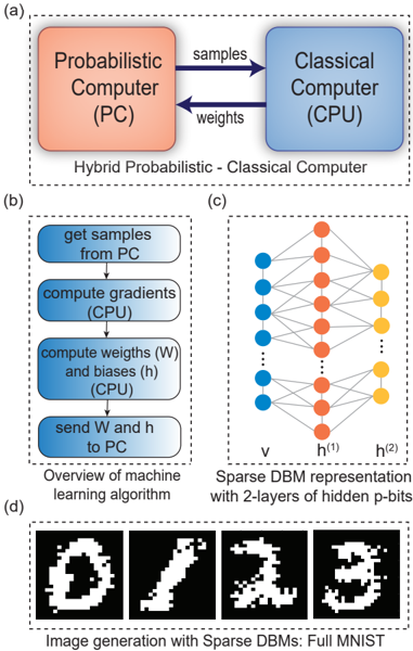
The image is a composite technical figure containing four distinct but related diagrams labeled (a), (b), (c), and (d). It illustrates the architecture, algorithmic workflow, network structure, and output of a machine learning system that combines a Probabilistic Computer (PC) with a Classical Computer (CPU) to train and run a Sparse Deep Belief Machine (DBM) for image generation.
### Components/Axes
The figure is divided into four dashed-line boxes, each with a caption:
* **(a) Top:** A block diagram titled "Hybrid Probabilistic - Classical Computer".
* **(b) Bottom Left:** A flowchart titled "Overview of machine learning algorithm".
* **(c) Bottom Right:** A neural network diagram titled "Sparse DBM representation with 2-layers of hidden p-bits".
* **(d) Bottom:** A series of images titled "Image generation with Sparse DBMs: Full MNIST".
### Detailed Analysis
**Part (a): Hybrid Computer Architecture**
* **Components:** Two main blocks.
* Left block (orange): Labeled "Probabilistic Computer (PC)".
* Right block (blue): Labeled "Classical Computer (CPU)".
* **Data Flow:** Two arrows indicate bidirectional communication.
* Arrow from PC to CPU: Labeled "samples".
* Arrow from CPU to PC: Labeled "weights".
**Part (b): Machine Learning Algorithm Flowchart**
* **Process Steps (in sequence, top to bottom):**
1. "get samples from PC" (Blue rounded rectangle)
2. "compute gradients (CPU)" (Blue rounded rectangle)
3. "compute weights (W) and biases (h) (CPU)" (Blue rounded rectangle)
4. "send W and h to PC" (Blue rounded rectangle)
* **Flow:** Vertical arrows connect the steps in the order listed above.
**Part (c): Sparse DBM Network Diagram**
* **Structure:** A three-layer neural network.
* **Leftmost Layer (Input/Visible):** Labeled "v". Consists of 5 blue circles (nodes).
* **Middle Layer (Hidden 1):** Labeled "h⁽¹⁾". Consists of 5 orange circles.
* **Rightmost Layer (Hidden 2):** Labeled "h⁽²⁾". Consists of 3 yellow circles.
* **Connections:** Lines connect nodes between adjacent layers. The connections appear dense between `v` and `h⁽¹⁾`, and sparser between `h⁽¹⁾` and `h⁽²⁾`, illustrating the "Sparse" property. Vertical ellipses (`...`) between nodes in layers `v` and `h⁽¹⁾` indicate these are representative subsets of a larger layer.
**Part (d): Generated Image Outputs**
* **Content:** Four black-and-white, pixelated images resembling handwritten digits.
* Image 1: Resembles a "0".
* Image 2: Resembles a "1".
* Image 3: Resembles a "2".
* Image 4: Resembles a "3".
* **Style:** The images are noisy and imperfect, characteristic of early-stage or generative model outputs.
### Key Observations
1. **Clear Division of Labor:** The system explicitly separates probabilistic sampling (PC) from deterministic gradient and weight calculations (CPU).
2. **Algorithmic Loop:** The flowchart in (b) defines a clear iterative training loop: sample -> compute gradients -> update parameters -> send new parameters back to the probabilistic hardware.
3. **Network Sparsity:** The diagram in (c) visually emphasizes a sparse connectivity pattern, particularly in the second hidden layer (`h⁽²⁾`), which has fewer nodes than the previous layers.
4. **Functional Demonstration:** Part (d) provides empirical evidence that the described hybrid system and Sparse DBM architecture can generate recognizable, albeit low-fidelity, images from the MNIST dataset.
### Interpretation
This composite figure presents a complete pipeline for a novel computing paradigm. It argues for the efficiency of using specialized probabilistic hardware (PC) for the sampling-intensive tasks inherent in training certain types of generative models (like DBMs), while leveraging conventional CPUs for the well-defined mathematical operations of gradient descent and parameter updates.
The **relationship between elements** is sequential and functional: (a) defines the hardware architecture, (b) details the software algorithm that runs on it, (c) specifies the model structure being trained, and (d) shows the tangible result of that training. The "Sparse" aspect of the DBM, highlighted in (c), is likely a key innovation aimed at reducing computational and memory overhead, making the hybrid approach more feasible.
The **notable trend** is the movement from abstract architecture (a) to concrete output (d). The **anomaly or point of interest** is the quality of the generated digits in (d); while recognizable, they are coarse, suggesting the system may be a proof-of-concept or that the sparsity constraint trades off some generative fidelity for efficiency. The figure collectively makes a case for heterogeneous computing architectures tailored to specific machine learning workloads.