## System Architecture Diagram: Automated Code Generation and Evaluation Pipeline
### Overview
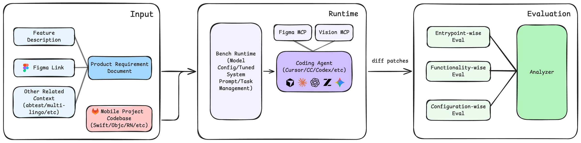
This image is a system architecture diagram illustrating a three-stage pipeline for automated code generation and evaluation. The flow moves from left to right, starting with input requirements and a codebase, proceeding through a runtime environment where a coding agent generates code, and concluding with a multi-faceted evaluation phase. The diagram uses color-coded boxes and directional arrows to show the flow of data and control.
### Components/Axes
The diagram is segmented into three primary containers, each with a title in the top-right corner:
1. **Input** (Left container)
2. **Runtime** (Center container)
3. **Evaluation** (Right container)
**Detailed Component List (with spatial grounding):**
* **Input Container (Left):**
* **Top-left:** A light blue box labeled `Feature Description`.
* **Middle-left:** A light blue box labeled `Figma Link`, accompanied by the Figma logo icon.
* **Bottom-left:** A light blue box labeled `Other Related Context (abtest/multi-lingo/etc)`.
* **Center:** A blue box labeled `Product Requirement Document`. Arrows from the three boxes above converge into this box.
* **Bottom-center:** A pink box labeled `Mobile Project Codebase (Swift/Objc/RN/etc)`, accompanied by the GitLab logo icon. An arrow from this box points towards the Runtime container.
* **Runtime Container (Center):**
* **Left side:** A large, light purple box labeled `Bench Runtime (Model Config/Tuned System Prompt/Task Management)`.
* **Right side:** A purple box labeled `Coding Agent (Cursor/CC/Codex/etc)`. Inside this box are five logos/icons representing different agents or tools: a cube, a sunburst, a spiral, a stylized "Z", and a star.
* **Top-right (above Coding Agent):** Two smaller, light purple boxes: `Figma MCP` and `Vision MCP`. Both have arrows pointing down to the `Coding Agent` box.
* **Flow:** An arrow from the `Product Requirement Document` (in Input) points to the `Bench Runtime`. An arrow from the `Bench Runtime` points to the `Coding Agent`. An arrow labeled `diff patches` exits the `Coding Agent` and points to the Evaluation container.
* **Evaluation Container (Right):**
* **Left side:** Three light green boxes stacked vertically:
* `Entrypoint-wise Eval` (Top)
* `Functionality-wise Eval` (Middle)
* `Configuration-wise Eval` (Bottom)
* **Right side:** A large, green box labeled `Analyzer`.
* **Flow:** Arrows from all three evaluation boxes (`Entrypoint-wise`, `Functionality-wise`, `Configuration-wise`) converge into the `Analyzer` box.
### Detailed Analysis
The diagram defines a clear, linear workflow:
1. **Input Stage:** Aggregates project context from multiple sources: a textual feature description, a design link (Figma), other contextual data (like A/B tests or multilingual requirements), and the existing mobile project codebase. These are synthesized into a Product Requirement Document.
2. **Runtime Stage:** The requirement document and codebase are fed into a "Bench Runtime," which manages model configuration, system prompts, and tasks. This runtime orchestrates a "Coding Agent" (e.g., Cursor, Claude Code, Codex). The agent is augmented by two Model Control Plane (MCP) modules: `Figma MCP` (likely for interpreting design files) and `Vision MCP` (for processing visual inputs). The agent's output is a set of `diff patches`.
3. **Evaluation Stage:** The generated code patches are subjected to three parallel evaluation tracks: checking entry points, assessing functionality, and verifying configuration. The results from all three evaluations are fed into a final `Analyzer` for synthesis and reporting.
### Key Observations
* **Modular Design:** The system is highly modular, with clear separation between input processing, code generation, and evaluation.
* **Agent-Centric Runtime:** The core of the runtime is a "Coding Agent," which is supported by specialized MCPs for design and vision, indicating a focus on multimodal input processing.
* **Comprehensive Evaluation:** The evaluation is not monolithic but is broken down into three distinct, complementary dimensions (entrypoint, functionality, configuration), suggesting a robust quality assurance process.
* **Tool Agnosticism:** The `Coding Agent` box lists multiple potential tools (Cursor, CC, Codex, etc.), indicating the architecture is designed to be agnostic to the specific agent implementation.
### Interpretation
This diagram represents a sophisticated, automated DevOps or MLOps pipeline specifically tailored for mobile application development. It demonstrates a Peircean investigative process where:
* **The Input stage** represents the **ground** or context—the raw materials of requirements and existing code.
* **The Runtime stage** is the **interpretant**—the active process (the coding agent) that generates a new sign (the code diff) based on the input.
* **The Evaluation stage** is the **object** being tested—the generated code is analyzed against multiple criteria to determine its validity and quality.
The pipeline's significance lies in its potential to drastically accelerate development cycles by automating the translation of design and requirements into code, followed by rigorous, multi-angle validation. The inclusion of `Figma MCP` and `Vision MCP` highlights a trend towards integrating design tools directly into the coding process, bridging the gap between design and implementation. The separation of evaluation into three specific "wise" tracks suggests that the system is designed to catch different classes of errors (e.g., structural issues via entrypoint eval, logical bugs via functionality eval, and environment mismatches via configuration eval), leading to higher overall code quality.