## Directed Graph Diagram: Four-Node Network with Color-Coded Relationships
### Overview
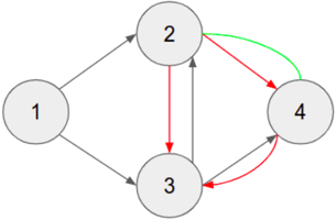
The image displays a directed graph (network diagram) consisting of four circular nodes, each labeled with a number (1, 2, 3, 4). The nodes are connected by directed arrows of three colors (black, red, green), indicating different types of relationships or flows between them. The layout is a diamond-like structure with node 1 on the left, node 2 at the top, node 3 at the bottom, and node 4 on the right.
### Components
* **Nodes:** Four gray-filled circles with black outlines, each containing a centered black numeral.
* Node 1: Leftmost position.
* Node 2: Top-center position.
* Node 3: Bottom-center position.
* Node 4: Rightmost position.
* **Edges (Arrows):** Directed connections between nodes, color-coded to denote different relationship types. There is no explicit legend provided in the image.
* **Black Arrows:** Appear to represent primary or standard directional flows.
* **Red Arrows:** Appear to represent reverse, feedback, or alternative flows.
* **Green Arrow:** A single, distinct connection, possibly indicating a special, privileged, or forward path.
### Detailed Analysis: Connection Inventory
The following lists all directed connections (edges) observed, with their source, target, color, and approximate visual path.
1. **Node 1 → Node 2:** Black arrow. Straight line sloping upward to the right.
2. **Node 1 → Node 3:** Black arrow. Straight line sloping downward to the right.
3. **Node 2 → Node 3:** Red arrow. Straight vertical line pointing downward.
4. **Node 2 → Node 4:** Green arrow. Curved line arcing over the top from left to right.
5. **Node 3 → Node 2:** Black arrow. Straight vertical line pointing upward.
6. **Node 3 → Node 4:** Black arrow. Straight line sloping upward to the right.
7. **Node 4 → Node 3:** Red arrow. Curved line arcing under the bottom from right to left.
### Key Observations
* **Bidirectional Links:** There are two pairs of nodes with connections in both directions, but using different colors:
* Between Node 2 and Node 3: A black arrow (3→2) and a red arrow (2→3).
* Between Node 3 and Node 4: A black arrow (3→4) and a red arrow (4→3).
* **Unique Connection:** The green arrow from Node 2 to Node 4 is the only connection of its color and is the only direct path from the top node (2) to the right node (4).
* **Node Connectivity:**
* Node 1 is a pure source, with two outgoing black arrows and no incoming arrows.
* Node 2 has two outgoing arrows (red to 3, green to 4) and two incoming arrows (black from 1, black from 3).
* Node 3 is the most connected node, with three outgoing arrows (black to 2, black to 4) and three incoming arrows (black from 1, red from 2, red from 4).
* Node 4 has one outgoing arrow (red to 3) and two incoming arrows (green from 2, black from 3).
### Interpretation
This diagram models a system with four states or components where interactions are not uniform. The color-coding suggests a taxonomy of relationships:
* **Black arrows** likely represent the default or foundational flow of control, information, or transition.
* **Red arrows** consistently point in the opposite direction of a corresponding black arrow (between 2↔3 and 3↔4), strongly implying they represent **feedback loops, reversals, or corrective pathways**. The system has built-in mechanisms to return from states 3 and 4 to their predecessors.
* The single **green arrow** (2→4) is notable. It creates a "shortcut" or privileged path that bypasses the intermediate node 3. This could represent a special condition, a high-priority transition, or an optimized route within the network.
The overall structure suggests a process that begins at Node 1, diverges into two interacting core components (Nodes 2 and 3), which then feed into a terminal or output component (Node 4). However, Node 4 is not a pure sink, as it feeds back into the core via Node 3, creating a **closed-loop system**. The bidirectional links between 2-3 and 3-4 indicate these pairs are in a dynamic, possibly regulatory, relationship. The absence of a direct link from Node 1 to Node 4 and the lack of a green arrow back from 4 to 2 are also significant, defining the boundaries and primary direction of the system's flow.