## Diagram: System Architecture for Fairness-Aware Specification Verification
### Overview
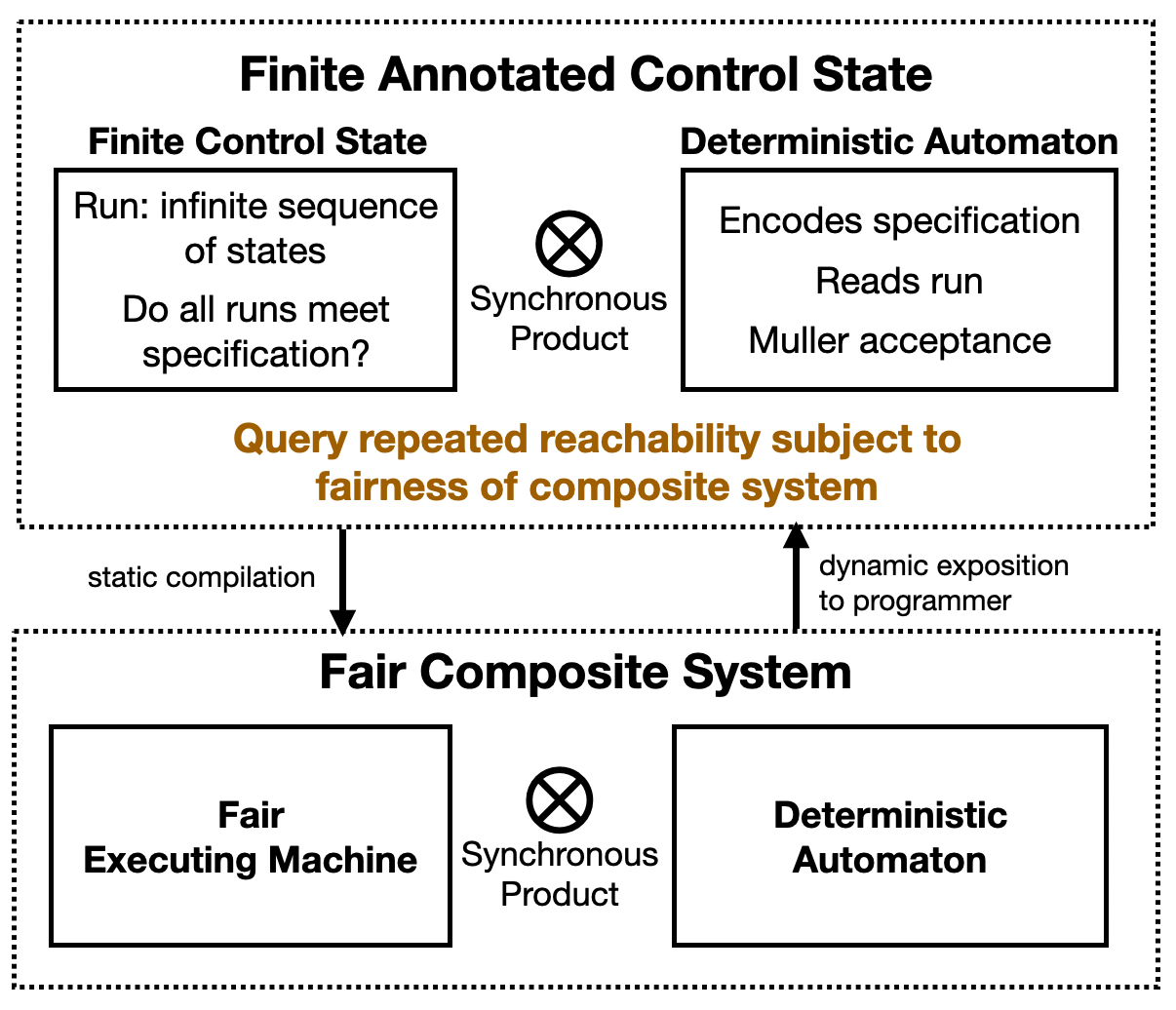
The image is a technical block diagram illustrating a two-layered system architecture for verifying system specifications against fairness constraints. It depicts a transformation process from a high-level, abstract model ("Finite Annotated Control State") to a concrete, executable model ("Fair Composite System"), with a feedback loop to the programmer. The diagram uses boxes, arrows, and symbolic operators to represent components, data flow, and operations.
### Components/Axes
The diagram is divided into two primary sections, each enclosed by a dotted rectangular border.
**1. Top Section: Finite Annotated Control State**
* **Title:** "Finite Annotated Control State" (centered at the top).
* **Left Component:** A solid-bordered rectangle labeled **"Finite Control State"**. Inside, the text reads:
* "Run: infinite sequence of states"
* "Do all runs meet specification?"
* **Right Component:** A solid-bordered rectangle labeled **"Deterministic Automaton"**. Inside, the text reads:
* "Encodes specification"
* "Reads run"
* "Muller acceptance"
* **Central Operator:** Between the two rectangles is a circle containing a cross (⊗), labeled **"Synchronous Product"**.
* **Central Query:** Below the two rectangles, centered and in a distinct brown/gold color, is the text: **"Query repeated reachability subject to fairness of composite system"**.
**2. Bottom Section: Fair Composite System**
* **Title:** "Fair Composite System" (centered at the top of this section).
* **Left Component:** A solid-bordered rectangle labeled **"Fair Executing Machine"**.
* **Right Component:** A solid-bordered rectangle labeled **"Deterministic Automaton"**.
* **Central Operator:** Between these two rectangles is another circle containing a cross (⊗), also labeled **"Synchronous Product"**.
**3. Connecting Flows (Between Sections)**
* **Downward Arrow:** A solid black arrow points from the central query in the top section down to the "Fair Composite System" section. It is labeled **"static compilation"**.
* **Upward Arrow:** A solid black arrow points from the "Fair Composite System" section back up to the central query area. It is labeled **"dynamic exposition to programmer"**.
### Detailed Analysis
The diagram describes a formal method workflow:
1. **Problem Formulation (Top Layer):** The core problem is defined as checking whether all possible infinite execution paths ("runs") of a system (represented by a "Finite Control State") satisfy a given specification. This specification is formally encoded by a "Deterministic Automaton" using "Muller acceptance" conditions (a type of condition for infinite runs). The interaction between the system model and the specification checker is modeled as a "Synchronous Product."
2. **Transformation:** The abstract verification problem ("Query repeated reachability...") is transformed into a concrete system via "static compilation." This suggests an automated translation process.
3. **Concrete System (Bottom Layer):** The result is a "Fair Composite System," which is also a synchronous product. This time, it combines a "Fair Executing Machine" (the concrete implementation of the system under test, with fairness guarantees) with a "Deterministic Automaton" (likely the compiled version of the specification).
4. **Feedback Loop:** The results or state of the concrete "Fair Composite System" are fed back to the programmer through "dynamic exposition." This implies a runtime or interactive debugging/analysis phase where the programmer can observe the system's behavior in relation to the specification.
### Key Observations
* **Symmetry and Repetition:** The "Synchronous Product" operator (⊗) and the "Deterministic Automaton" component appear in both the abstract and concrete layers, highlighting a consistent formal framework.
* **Color Coding:** The central query is the only text in a non-black color (brown/gold), emphasizing it as the pivotal problem statement driving the entire architecture.
* **Flow Direction:** The primary flow is top-down (compilation), but a critical feedback loop (dynamic exposition) flows bottom-up, indicating an interactive or iterative verification process.
* **Abstraction Gradient:** The top layer deals with abstract, infinite-state concepts ("infinite sequence of states"), while the bottom layer uses more concrete, executable terms ("Executing Machine").
### Interpretation
This diagram outlines a methodology for **formal verification of fair systems**. It bridges the gap between high-level specification and low-level execution.
* **What it demonstrates:** It shows how a complex verification question—"Does my system always behave fairly and meet its specification?"—can be systematically decomposed. The abstract model is used for formal reasoning, while the compiled composite system allows for concrete analysis or testing.
* **Relationships:** The "Synchronous Product" is the key combinator, merging the system's behavior with the specification's checker. The "static compilation" is the bridge from theory to practice, and "dynamic exposition" closes the loop, making the formal results accessible to a human developer.
* **Notable Concept:** The focus on **"fairness"** is critical. In verification, fairness constraints ensure that the system doesn't indefinitely postpone certain events (e.g., a request is eventually serviced). The architecture is explicitly designed to handle this, as seen in the query and the "Fair Executing Machine."
* **Underlying Framework:** The mention of "Muller acceptance" strongly suggests this architecture is grounded in **automata theory over infinite words**, a common framework for specifying and verifying reactive systems (like operating systems or controllers) that run continuously.
In essence, the image depicts a pipeline for rigorously checking that a system's implementation adheres to its fairness-aware specification, providing both automated compilation and a means for programmer insight.