## Process Flow Diagram: Goal / Rule Synthesizer
### Overview
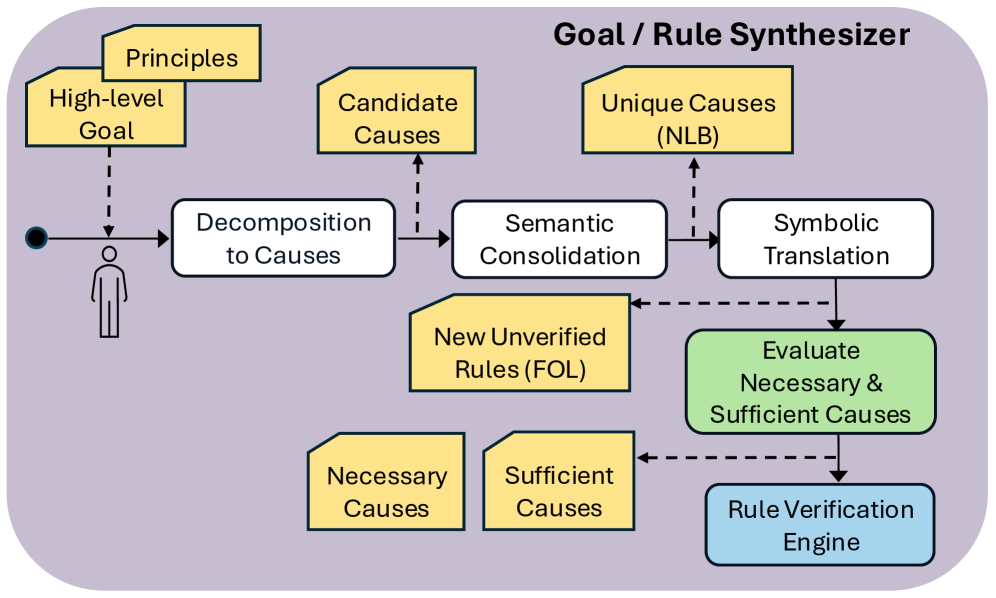
The image depicts a logical workflow diagram titled "Goal / Rule Synthesizer." It illustrates a multi-stage process for transforming high-level human goals and principles into verified logical rules. The diagram utilizes a left-to-right primary flow, supplemented by various data inputs (yellow artifacts) and feedback loops (dashed lines).
### Components/Axes
The diagram is organized into a linear process flow with auxiliary data inputs.
**1. Primary Process Nodes (White Rectangles):**
* **Decomposition to Causes:** The first processing step.
* **Semantic Consolidation:** The second processing step.
* **Symbolic Translation:** The third processing step.
**2. Specialized Process Nodes:**
* **Evaluate Necessary & Sufficient Causes (Green Rectangle):** Located in the bottom-right quadrant, this acts as a decision or evaluation gate.
* **Rule Verification Engine (Blue Rectangle):** The final stage of the process, located at the bottom right.
**3. Data/Artifact Inputs (Yellow Document Icons):**
* **Principles** (Top-left)
* **High-level Goal** (Top-left)
* **Candidate Causes** (Top-center)
* **Unique Causes (NLB)** (Top-right)
* **New Unverified Rules (FOL)** (Center)
* **Necessary Causes** (Bottom-left)
* **Sufficient Causes** (Bottom-center)
**4. Flow Indicators:**
* **Solid Arrows:** Represent the primary, sequential progression of the workflow.
* **Dashed Arrows:** Represent dependencies, data inputs, or feedback loops.
* **Start Point:** A black dot on the far left initiates the flow.
* **User Icon:** A stylized human figure represents the source of the initial input.
### Detailed Analysis
**The Workflow Sequence:**
1. **Initiation:** The process begins at the black dot. A user provides input, which is informed by "Principles" and "High-level Goal" (indicated by dashed arrows pointing to the main flow line).
2. **Decomposition:** The flow enters the "Decomposition to Causes" node. A dashed arrow points upward to "Candidate Causes," suggesting this node generates or identifies these causes.
3. **Consolidation:** The flow proceeds to "Semantic Consolidation." A dashed arrow points upward to "Unique Causes (NLB)."
4. **Translation:** The flow proceeds to "Symbolic Translation." A dashed arrow points upward to "New Unverified Rules (FOL)."
5. **Evaluation:** The output of "Symbolic Translation" flows downward into the green "Evaluate Necessary & Sufficient Causes" node.
* This node receives additional inputs from "Necessary Causes" and "Sufficient Causes" (dashed arrows pointing rightward into the node).
* There is a feedback loop (dashed arrow) pointing from the green node back to "Semantic Consolidation," suggesting that if evaluation fails, the system iterates.
6. **Verification:** The final output flows from the green node into the blue "Rule Verification Engine."
### Key Observations
* **Terminology:**
* **NLB:** Likely refers to "Natural Language Base" or "Natural Language Bridge," given the context of semantic consolidation.
* **FOL:** Standard abbreviation for "First-Order Logic," confirming the transition from semantic/natural language to formal logic.
* **Iterative Design:** The presence of dashed feedback loops (specifically from the "Evaluate" node back to "Semantic Consolidation" and from "New Unverified Rules" back to "Semantic Consolidation") indicates that this is a recursive or iterative system rather than a strictly linear one.
* **Color Coding:**
* **Yellow:** Represents external inputs, knowledge bases, or intermediate artifacts.
* **White:** Represents core processing logic.
* **Green:** Represents the evaluation/validation logic.
* **Blue:** Represents the final execution/verification environment.
### Interpretation
This diagram represents a system architecture designed to bridge the gap between human intent and machine-executable logic.
The process demonstrates a "translation pipeline":
1. **Abstraction to Concrete:** It starts with abstract human concepts ("High-level Goal," "Principles") and decomposes them into concrete "Causes."
2. **Semantic to Symbolic:** It moves from "Semantic Consolidation" (likely handling natural language or conceptual grouping) to "Symbolic Translation" (converting concepts into formal logic, i.e., FOL).
3. **Validation:** The system does not assume the generated rules are correct. It explicitly includes an "Evaluate Necessary & Sufficient Causes" step, which acts as a quality control gate before the rules reach the "Rule Verification Engine."
The architecture suggests a robust, iterative approach where the system refines its rule set based on the evaluation of necessary and sufficient conditions, ensuring that the final rules are logically sound before they are verified.