## Diagram: Cube 3-View Projection and Left View Construction
### Overview
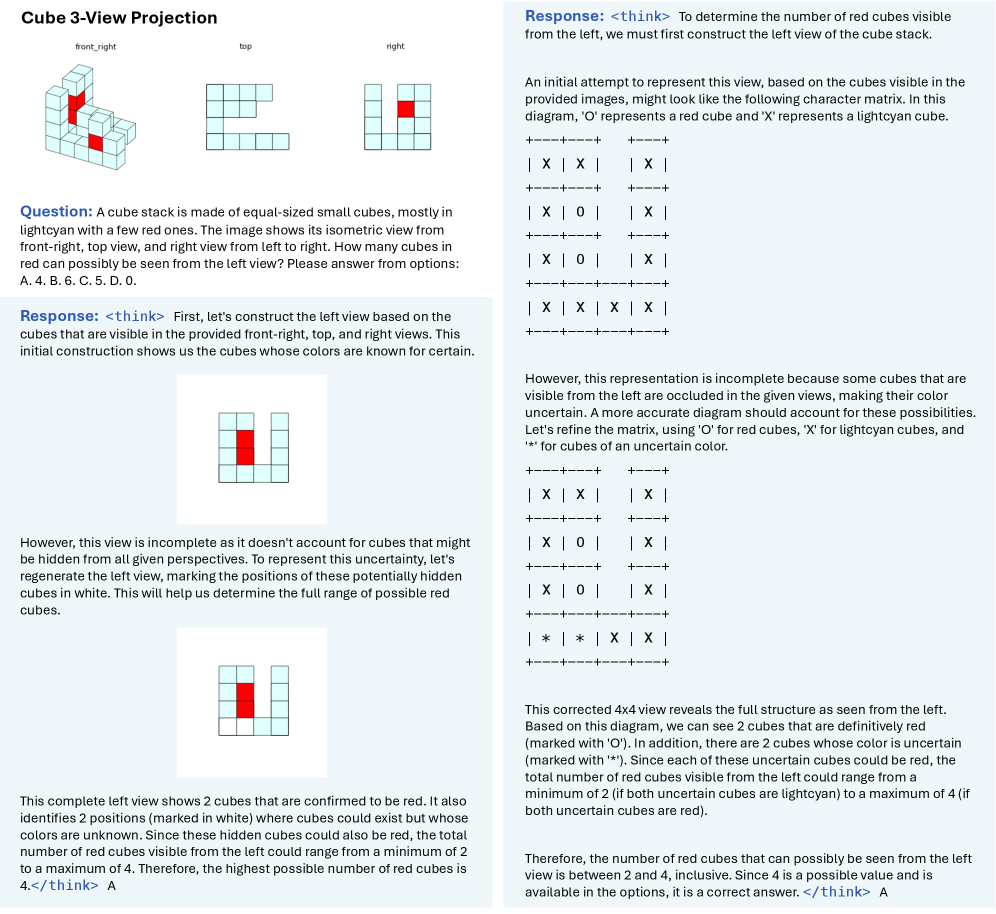
The image presents a problem involving a cube stack made of lightcyan and red cubes. It shows the isometric view of the cube stack from front-right, top, and right perspectives. The task is to determine how many red cubes can be seen from the left view. The image then provides a step-by-step construction of the left view, accounting for hidden cubes and color uncertainties, ultimately arriving at the answer.
### Components/Axes
* **Title:** Cube 3-View Projection
* **Views:**
* front_right (isometric view of the cube stack)
* top (top view of the cube stack)
* right (right view of the cube stack)
* **Question:** A text block posing the problem and providing multiple-choice answers.
* **Response:** A step-by-step explanation and construction of the left view.
* **Cube Colors:** lightcyan and red.
* **Character Matrix Legend:** 'O' represents a red cube, 'X' represents a lightcyan cube, and '*' represents a cube of uncertain color.
### Detailed Analysis or ### Content Details
1. **Problem Statement:**
* A cube stack is made of equal-sized small cubes, mostly in lightcyan with a few red ones.
* The image shows its isometric view from front-right, top view, and right view from left to right.
* Question: How many cubes in red can possibly be seen from the left view?
* Options: A. 4. B. 6. C. 5. D. 0.
2. **Initial Response:**
* Construct the left view based on the provided front-right, top, and right views.
* The initial construction shows the cubes whose colors are known for certain.
* A 4x4 grid shows the initial left view with one red cube ('O') and the rest lightcyan ('X').
3. **Accounting for Hidden Cubes:**
* The initial view is incomplete as it doesn't account for cubes that might be hidden from all given perspectives.
* Regenerate the left view, marking the positions of these potentially hidden cubes in white.
* A 3x3 grid shows the left view with one red cube and two white cubes.
4. **Complete Left View:**
* The complete left view shows 2 cubes that are confirmed to be red.
* It also identifies 2 positions (marked in white) where cubes could exist but whose colors are unknown.
* Since these hidden cubes could also be red, the total number of red cubes visible from the left could range from a minimum of 2 to a maximum of 4.
* Therefore, the highest possible number of red cubes is 4.
5. **Character Matrix Refinement:**
* The initial representation is incomplete because some cubes that are visible from the left are occluded in the given views, making their color uncertain.
* Refine the matrix, using 'O' for red cubes, 'X' for lightcyan cubes, and '*' for cubes of an uncertain color.
* A 4x4 character matrix is presented: