## Diagram: Binary Tree Operations
### Overview
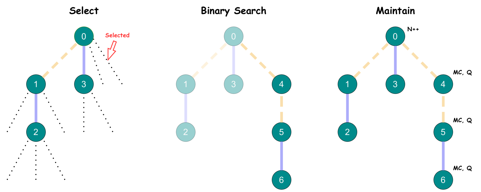
The image illustrates three binary tree operations: Select, Binary Search, and Maintain. Each operation is represented by a binary tree diagram showing nodes and connections. The diagrams highlight different aspects of how these operations might traverse or modify the tree structure.
### Components/Axes
* **Nodes:** Represented by teal circles, each containing a numerical value.
* **Edges:** Represented by lines connecting the nodes. Solid blue lines indicate a direct connection, while dashed yellow lines indicate a potential path or selection.
* **Labels:**
* Titles: "Select", "Binary Search", "Maintain" are placed above their respective diagrams.
* Node Values: Integers from 0 to 6 are used to label the nodes.
* Annotations: "Selected" with an arrow in the "Select" diagram, "N++" near node 0 in the "Maintain" diagram, and "MC, Q" near nodes 4, 5, and 6 in the "Maintain" diagram.
### Detailed Analysis
**1. Select (Left Diagram)**
* **Structure:** A binary tree with nodes labeled 0, 1, 2, and 3.
* **Connections:**
* Node 0 is connected to nodes 1 and 3 with solid blue lines.
* Node 1 is connected to node 2 with a solid blue line.
* Dotted lines extend from nodes 1, 2, and 3, indicating potential further branches.
* **Selection:** A dashed yellow line connects node 0 to node 1. A red arrow points to this connection, labeled "Selected".
**2. Binary Search (Middle Diagram)**
* **Structure:** A binary tree with nodes labeled 0, 1, 2, 3, 4, 5, and 6.
* **Connections:**
* Node 0 is connected to nodes 1 and 3 with solid blue lines.
* Node 1 is connected to node 2 with a solid blue line.
* Node 0 is connected to node 4 with a dashed yellow line.
* Node 4 is connected to node 5 with a dashed yellow line.
* Node 5 is connected to node 6 with a solid blue line.
**3. Maintain (Right Diagram)**
* **Structure:** A binary tree with nodes labeled 0, 1, 2, 3, 4, 5, and 6.
* **Connections:**
* Node 0 is connected to nodes 1 and 3 with dashed yellow lines.
* Node 1 is connected to node 2 with a solid blue line.
* Node 3 is connected to node 0 with a solid blue line.
* Node 0 is connected to node 4 with a dashed yellow line.
* Node 4 is connected to node 5 with a dashed yellow line.
* Node 5 is connected to node 6 with a solid blue line.
* **Annotations:**
* "N++" is located near node 0.
* "MC, Q" is located near nodes 4, 5, and 6.
### Key Observations
* The "Select" diagram focuses on choosing a specific path within the tree.
* The "Binary Search" diagram illustrates a search path through the tree.
* The "Maintain" diagram shows a tree structure with additional annotations, possibly indicating maintenance operations or metadata.
### Interpretation
The diagrams provide a high-level overview of three binary tree operations. The "Select" operation highlights the process of choosing a specific node or path. The "Binary Search" operation demonstrates how a search algorithm might traverse the tree. The "Maintain" operation suggests modifications or updates to the tree structure, possibly involving metadata or queue management ("MC, Q"). The "N++" annotation might indicate an increment operation on a node counter or identifier. The use of dashed yellow lines versus solid blue lines likely indicates a distinction between potential paths (yellow) and confirmed connections (blue).