## Diagrams: Algorithm Visualization
### Overview
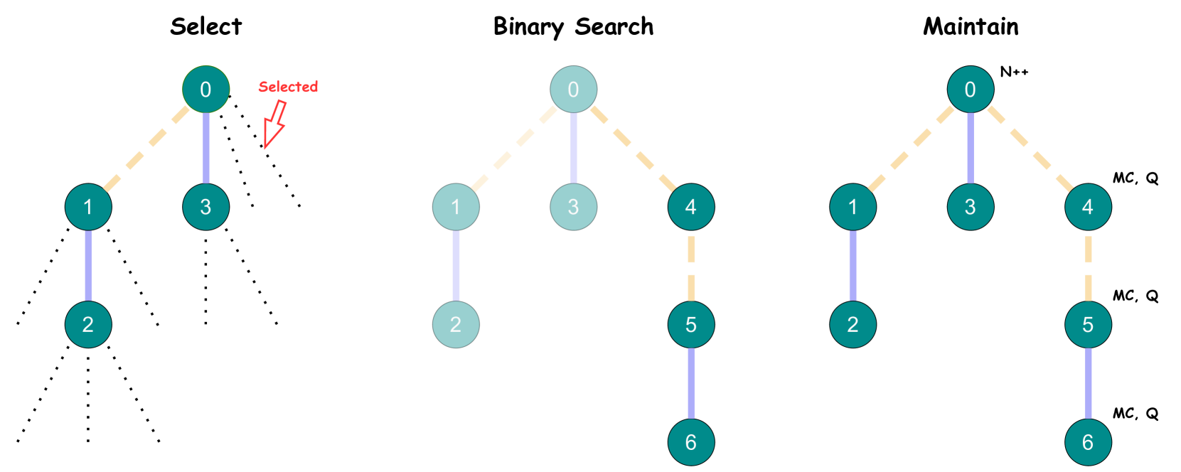
The image contains three interconnected diagrams labeled **"Select"**, **"Binary Search"**, and **"Maintain"**, each depicting hierarchical node structures with numerical labels and color-coded connections. Arrows, annotations, and color schemes suggest relationships between nodes and operational states.
---
### Components/Axes
#### **Select Diagram**
- **Nodes**:
- `0` (teal, selected with a red arrow labeled "Selected").
- `1`, `2`, `3` (teal, connected via dotted lines to `0`).
- **Connections**:
- Dotted lines from `0` to `1`, `3`, and `2` (with `2` having additional dotted branches).
#### **Binary Search Diagram**
- **Nodes**:
- `0` (light blue, central node).
- `1`, `2` (light blue, connected to `0`).
- `3`, `4`, `5`, `6` (teal, connected via solid lines).
- **Connections**:
- Solid lines from `0` to `3` and `1`; `3` connects to `4` and `2`; `4` connects to `5` and `6`.
#### **Maintain Diagram**
- **Nodes**:
- `0` (teal, labeled "N++").
- `1`, `2`, `3`, `4`, `5`, `6` (dark teal, with annotations).
- **Connections**:
- Solid lines from `0` to `3` and `4`; `3` connects to `1` and `2`; `4` connects to `5` and `6`.
- **Annotations**:
- Right-side labels: `N++`, `MC`, `Q` (likely representing operations or states).
---
### Detailed Analysis
#### **Select Diagram**
- Node `0` is explicitly marked as "Selected" with a red arrow.
- Dotted lines suggest tentative or alternative connections to nodes `1`, `2`, and `3`.
#### **Binary Search Diagram**
- Color differentiation:
- Light blue nodes (`0`, `1`, `2`) may represent initial or active states.
- Teal nodes (`3`, `4`, `5`, `6`) likely denote deeper or resolved states.
- Hierarchical flow: `0` → `3` → `4` → `5`/`6`, with `2` as a secondary branch.
#### **Maintain Diagram**
- Node `0` is labeled "N++", implying an increment operation.
- Annotations `MC` (possibly "Memory Counter") and `Q` (possibly "Queue") on the right suggest auxiliary processes.
- Dark teal nodes (`1`, `2`, `3`, `4`, `5`, `6`) may represent persistent or updated states.
---
### Key Observations
1. **Color Coding**:
- Teal and light blue nodes differentiate primary vs. secondary states across diagrams.
- Dark teal in "Maintain" suggests updated or finalized states.
2. **Flow Direction**:
- "Select" and "Binary Search" use top-down branching, while "Maintain" combines top-down and right-side annotations.
3. **Annotations**:
- "N++" in "Maintain" implies iterative updates.
- "MC" and `Q` hint at memory and queue management, common in algorithmic workflows.
---
### Interpretation
- **Purpose**:
- **Select**: Visualizes node selection, possibly for tree/graph algorithms.
- **Binary Search**: Illustrates a search process with hierarchical decision points.
- **Maintain**: Depicts state management, including increments (`N++`), memory (`MC`), and queuing (`Q`).
- **Relationships**:
- The diagrams may represent stages of an algorithm: selection → search → maintenance.
- Color transitions (e.g., light blue → teal → dark teal) could indicate progression through states.
- **Anomalies**:
- The "Select" diagram’s dotted lines lack clear directionality, suggesting ambiguity in connections.
- The "Maintain" diagram’s right-side annotations (`MC`, `Q`) are spatially isolated, possibly indicating auxiliary processes.
- **Significance**:
- The diagrams likely model computational workflows, emphasizing decision-making (`Select`), search efficiency (`Binary Search`), and resource management (`Maintain`).
- The use of color and annotations provides a visual guide for tracking state changes and operational priorities.