## Layered System Diagram: Abstraction Layers in a System
### Overview
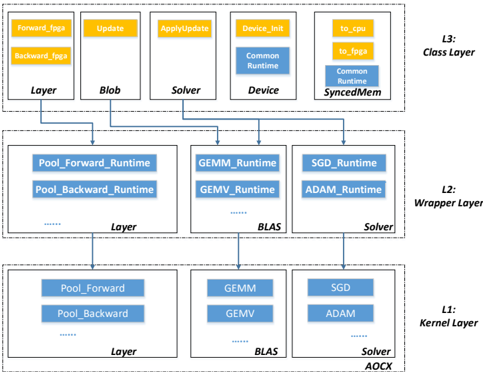
The image is a diagram illustrating a layered system architecture, likely related to software or hardware design. It depicts three distinct layers (L1, L2, L3) representing different levels of abstraction. Each layer contains components grouped under categories like "Layer," "Blob," "Solver," "Device," and "BLAS." The diagram shows the relationships and dependencies between these components across the layers.
### Components/Axes
* **Layers:** The diagram is structured into three horizontal layers, labeled L1, L2, and L3.
* L1: Kernel Layer
* L2: Wrapper Layer
* L3: Class Layer
* **Categories:** Within each layer, components are grouped under the following categories:
* Layer
* Blob
* Solver
* Device
* BLAS
* AOCX (appears only in L1)
* **Components:** Each category contains specific components, represented as rectangular boxes. The components vary across the layers.
* **Connections:** Arrows indicate the flow or dependency between components in different layers.
### Detailed Analysis or ### Content Details
**L3: Class Layer (Top Layer)**
* **Layer:**
* Forward_fpga (yellow fill)
* Backward_fpga (yellow fill)
* **Blob:**
* Update (yellow fill)
* **Solver:**
* ApplyUpdate (yellow fill)
* **Device:**
* Device_Init (yellow fill)
* Common Runtime (blue fill)
* **SyncedMem:**
* to_cpu (yellow fill)
* to_fpga (yellow fill)
* Common Runtime (blue fill)
**L2: Wrapper Layer (Middle Layer)**
* **Layer:**
* Pool_Forward_Runtime (blue fill)
* Pool_Backward_Runtime (blue fill)
* Ellipsis (...) indicating more components
* **BLAS:**
* GEMM_Runtime (blue fill)
* GEMV_Runtime (blue fill)
* Ellipsis (...) indicating more components
* **Solver:**
* SGD_Runtime (blue fill)
* ADAM_Runtime (blue fill)
**L1: Kernel Layer (Bottom Layer)**
* **Layer:**
* Pool_Forward (blue fill)
* Pool_Backward (blue fill)
* Ellipsis (...) indicating more components
* **BLAS:**
* GEMM (blue fill)
* GEMV (blue fill)
* **Solver:**
* SGD (blue fill)
* ADAM (blue fill)
* **AOCX**
### Key Observations
* The diagram illustrates a hierarchical structure, with each layer providing a different level of abstraction.
* The "Layer," "Blob," and "Solver" categories are present in all three layers, but the specific components within them change.
* The arrows indicate dependencies between components in different layers, suggesting a flow of data or control.
* The use of "Runtime" in the L2 components suggests that this layer provides runtime implementations of the components in L1.
* The yellow fill in L3 may indicate configuration or initialization components.
### Interpretation
The diagram represents a layered system architecture, where each layer abstracts away the complexities of the underlying layers. The Kernel Layer (L1) likely contains the core functionalities, while the Wrapper Layer (L2) provides runtime implementations or interfaces for these functionalities. The Class Layer (L3) provides a higher-level interface for interacting with the system.
The connections between the layers suggest a flow of data or control from the Class Layer down to the Kernel Layer and potentially back up. The "Runtime" components in the Wrapper Layer likely handle the execution and management of the Kernel Layer components.
The use of different categories (Layer, Blob, Solver, Device, BLAS) suggests that the system is composed of different types of components, each with its own specific role. The presence of "fpga" in some of the L3 components suggests that the system may involve hardware acceleration using FPGAs.
The diagram provides a high-level overview of the system architecture and can be used to understand the relationships and dependencies between different components.