## Tree Diagram: Hierarchical Node Structure
### Overview
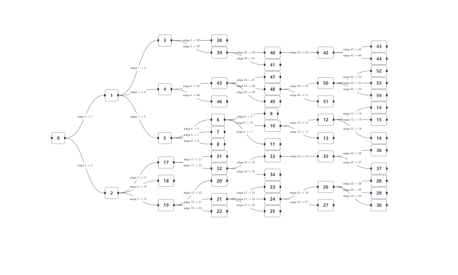
The image presents a tree diagram illustrating a hierarchical structure with nodes labeled numerically and connected by edges. The diagram starts from a root node and branches out to multiple levels, showing relationships between the nodes. Each edge is labeled to indicate the connection between nodes.
### Components/Axes
* **Nodes:** Represented as rounded rectangles, each containing a unique numerical identifier. The node IDs range from 0 to 54.
* **Edges:** Represented as curved lines connecting the nodes. Each edge is labeled in the format "edge X -> Y", where X and Y are the numerical identifiers of the connected nodes.
* **Root Nodes:** The diagram originates from nodes 0, 1, and 2.
* **Leaf Nodes:** Nodes at the end of the branches, such as 14, 15, 16, 22, 25, 27, 28, 29, 30, 36, 37, 38, 39, 43, 44, 46, 47, 49, 51, 52, 53, and 54.
### Detailed Analysis or ### Content Details
* **Node 0:** Has two outgoing edges:
* edge 0 -> 1
* edge 0 -> 2
* **Node 1:** Has three outgoing edges:
* edge 1 -> 3
* edge 1 -> 4
* edge 1 -> 5
* **Node 2:** Has three outgoing edges:
* edge 2 -> 17
* edge 2 -> 18
* edge 2 -> 19
* **Node 3:** Has two outgoing edges:
* edge 3 -> 38
* edge 3 -> 39
* **Node 4:** Has two outgoing edges:
* edge 4 -> 45
* edge 4 -> 46
* **Node 5:** Has three outgoing edges:
* edge 5 -> 6
* edge 5 -> 7
* edge 5 -> 8
* **Node 6:** Has three outgoing edges:
* edge 6 -> 9
* edge 6 -> 10
* edge 6 -> 11
* **Node 17:** Has two outgoing edges:
* edge 17 -> 31
* edge 17 -> 32
* **Node 19:** Has three outgoing edges:
* edge 19 -> 20
* edge 19 -> 21
* edge 19 -> 22
* **Node 39:** Has two outgoing edges:
* edge 39 -> 40
* edge 39 -> 41
* **Node 45:** Has three outgoing edges:
* edge 45 -> 47
* edge 45 -> 48
* edge 45 -> 49
* **Node 48:** Has two outgoing edges:
* edge 48 -> 50
* edge 48 -> 51
* **Node 10:** Has two outgoing edges:
* edge 10 -> 12
* edge 10 -> 13
* **Node 32:** Has two outgoing edges:
* edge 32 -> 33
* edge 32 -> 34
* **Node 21:** Has three outgoing edges:
* edge 21 -> 23
* edge 21 -> 24
* edge 21 -> 25
* **Node 40:** Has one outgoing edge:
* edge 40 -> 42
* **Node 42:** Has two outgoing edges:
* edge 42 -> 43
* edge 42 -> 44
* **Node 50:** Has three outgoing edges:
* edge 50 -> 52
* edge 50 -> 53
* edge 50 -> 54
* **Node 12:** Has three outgoing edges:
* edge 12 -> 14
* edge 12 -> 15
* edge 12 -> 16
* **Node 33:** Has one outgoing edge:
* edge 33 -> 35
* **Node 24:** Has two outgoing edges:
* edge 24 -> 26
* edge 24 -> 27
* **Node 35:** Has two outgoing edges:
* edge 35 -> 36
* edge 35 -> 37
* **Node 26:** Has three outgoing edges:
* edge 26 -> 28
* edge 26 -> 29
* edge 26 -> 30
### Key Observations
* The diagram represents a directed acyclic graph (DAG).
* The branching factor varies across different nodes. Some nodes have two or three outgoing edges, while others have only one.
* The diagram shows a clear hierarchical structure, with nodes at higher levels branching out to nodes at lower levels.
### Interpretation
The tree diagram illustrates a hierarchical relationship between different entities represented by the nodes. The edges indicate the flow or connection between these entities. The diagram could represent various systems, such as organizational structures, decision trees, or data flow in a computer program. The specific meaning depends on the context in which the diagram is used. The varying branching factors suggest that some entities have more direct relationships or dependencies than others. The diagram provides a visual representation of the relationships and dependencies within the system.