TECHNICAL ASSET FINGERPRINT
8ebc35f85da073d6edee0ab7
Click to view fullscreen
Press ESC or click to close
FOUND IN PAPERS
EXPERT: healer-alpha-free VERSION 1
RUNTIME: free/openrouter/healer-alpha
INTEL_VERIFIED
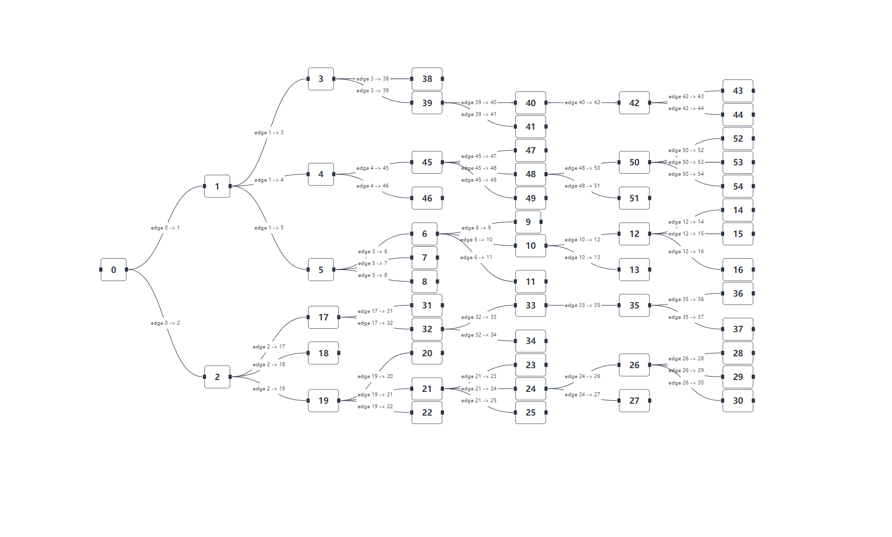
## Directed Graph Diagram: Hierarchical Network Structure
### Overview
The image displays a directed graph (or tree-like network) with numbered nodes connected by labeled edges. The graph originates from a single root node (0) on the left and expands rightward through multiple hierarchical levels. The structure is not a perfect tree, as some nodes have multiple parents (e.g., node 40 has two incoming edges). The layout is organized to minimize edge crossings, with nodes arranged in vertical columns representing different levels of depth from the root.
### Components/Axes
* **Nodes:** Rectangular boxes containing integer identifiers. There are no other labels or attributes on the nodes.
* **Edges:** Directed lines connecting nodes, each labeled with text in the format `edge [Source Node] -> [Target Node]`.
* **Layout:** The graph flows from left (root) to right (leaf nodes). Nodes are positioned in approximate vertical columns.
* **Column 1 (Leftmost):** Node 0.
* **Column 2:** Nodes 1, 2.
* **Column 3:** Nodes 3, 4, 5, 17, 18, 19.
* **Column 4:** Nodes 6, 7, 8, 20, 21, 22, 31, 32, 38, 39, 45, 46.
* **Column 5:** Nodes 9, 10, 11, 23, 24, 25, 33, 34, 40, 41, 47, 48, 49.
* **Column 6:** Nodes 12, 13, 26, 27, 35, 42, 50, 51.
* **Column 7 (Rightmost):** Nodes 14, 15, 16, 28, 29, 30, 36, 37, 43, 44, 52, 53, 54.
### Detailed Analysis
The graph's connectivity is defined entirely by the labeled edges. Below is a complete reconstruction of the network structure, tracing paths from the root.
**Root and First Level:**
* Node `0` has two outgoing edges:
* `edge 0 -> 1` (to Node 1)
* `edge 0 -> 2` (to Node 2)
**Branch from Node 1:**
* Node `1` has three outgoing edges:
* `edge 1 -> 3` (to Node 3)
* `edge 1 -> 4` (to Node 4)
* `edge 1 -> 5` (to Node 5)
**Branch from Node 2:**
* Node `2` has three outgoing edges:
* `edge 2 -> 17` (to Node 17)
* `edge 2 -> 18` (to Node 18)
* `edge 2 -> 19` (to Node 19)
**Sub-branches (Continuing from Level 3 nodes):**
* **From Node 3:**
* `edge 3 -> 38` (to Node 38)
* `edge 3 -> 39` (to Node 39)
* **From Node 4:**
* `edge 4 -> 45` (to Node 45)
* `edge 4 -> 46` (to Node 46)
* **From Node 5:**
* `edge 5 -> 6` (to Node 6)
* `edge 5 -> 7` (to Node 7)
* `edge 5 -> 8` (to Node 8)
* **From Node 17:**
* `edge 17 -> 31` (to Node 31)
* `edge 17 -> 32` (to Node 32)
* **From Node 19:**
* `edge 19 -> 20` (to Node 20)
* `edge 19 -> 21` (to Node 21)
* `edge 19 -> 22` (to Node 22)
**Deeper Connections (Level 4 and beyond):**
* **From Node 39:** `edge 39 -> 40` (to Node 40), `edge 39 -> 41` (to Node 41)
* **From Node 45:** `edge 45 -> 47` (to Node 47), `edge 45 -> 48` (to Node 48), `edge 45 -> 49` (to Node 49)
* **From Node 6:** `edge 6 -> 9` (to Node 9), `edge 6 -> 10` (to Node 10), `edge 6 -> 11` (to Node 11)
* **From Node 32:** `edge 32 -> 33` (to Node 33), `edge 32 -> 34` (to Node 34)
* **From Node 21:** `edge 21 -> 23` (to Node 23), `edge 21 -> 24` (to Node 24), `edge 21 -> 25` (to Node 25)
* **From Node 40:** `edge 40 -> 42` (to Node 42)
* **From Node 48:** `edge 48 -> 50` (to Node 50), `edge 48 -> 51` (to Node 51)
* **From Node 10:** `edge 10 -> 12` (to Node 12), `edge 10 -> 13` (to Node 13)
* **From Node 33:** `edge 33 -> 35` (to Node 35)
* **From Node 24:** `edge 24 -> 26` (to Node 26), `edge 24 -> 27` (to Node 27)
* **From Node 42:** `edge 42 -> 43` (to Node 43), `edge 42 -> 44` (to Node 44)
* **From Node 50:** `edge 50 -> 52` (to Node 52), `edge 50 -> 53` (to Node 53), `edge 50 -> 54` (to Node 54)
* **From Node 12:** `edge 12 -> 14` (to Node 14), `edge 12 -> 15` (to Node 15), `edge 12 -> 16` (to Node 16)
* **From Node 35:** `edge 35 -> 36` (to Node 36), `edge 35 -> 37` (to Node 37)
* **From Node 26:** `edge 26 -> 28` (to Node 28), `edge 26 -> 29` (to Node 29), `edge 26 -> 30` (to Node 30)
**Leaf Nodes (No Outgoing Edges):**
The following nodes appear at the far right of the diagram and have no outgoing edges: 38, 41, 46, 47, 49, 7, 8, 9, 11, 20, 22, 23, 25, 34, 43, 44, 51, 52, 53, 54, 13, 14, 15, 16, 27, 28, 29, 30, 36, 37.
### Key Observations
1. **Asymmetric Branching:** The branching factor varies significantly. Node 0 has 2 children, Node 1 has 3, Node 5 has 3, but Node 45 has 3 and Node 39 has 2. There is no uniform pattern.
2. **Depth Variation:** The maximum depth from the root is 7 levels (e.g., path 0 -> 1 -> 4 -> 45 -> 48 -> 50 -> 52). Some branches terminate much earlier (e.g., 0 -> 2 -> 18 ends at depth 3).
3. **Node Numbering:** Node numbers are not assigned sequentially by level or branch. They appear somewhat arbitrary, with low numbers (e.g., 6, 7, 8, 9, 10) appearing deep in the structure alongside high numbers (e.g., 45, 46, 47).
4. **Multiple Parents:** Node 40 is a convergence point, receiving edges from both Node 39 and Node 41 (though the edge from 41 is not explicitly drawn, the label `edge 39 -> 41` suggests 41 is a sibling, not a parent). *Correction:* Upon closer inspection, Node 41 is a sibling of Node 40, both children of Node 39. The only node with an apparent dual parent in the drawn edges is Node 40, which receives `edge 39 -> 40`. No other node has two incoming edge labels pointing to it.
5. **Visual Grouping:** Nodes are clustered visually by their parent, creating distinct sub-trees (e.g., the sub-tree under Node 5 is visually separate from the sub-tree under Node 4).
### Interpretation
This diagram represents a complex, directed acyclic graph (DAG) or a general graph (cycles cannot be ruled out without a full adjacency list, but none are visually apparent). It likely models a process flow, a dependency network, a state machine, or a organizational/software architecture hierarchy.
* **Information Flow:** The direction of edges indicates a one-way flow of control, data, or dependency from the root (0) towards the leaf nodes. The root is the sole source, and the leaves are terminal states or outputs.
* **Structural Complexity:** The non-uniform branching and varying depth suggest a system with heterogeneous components or processes. Some pathways are simple and direct, while others are highly elaborated.
* **Potential Anomaly:** The node numbering scheme is non-intuitive. In a typical technical diagram, numbering often follows a logical pattern (e.g., breadth-first or depth-first order). The apparent randomness here could indicate these are unique identifiers from a database or system, not labels chosen for diagrammatic clarity.
* **Purpose:** Without external context, the specific domain is unknown. However, the structure is consistent with representing: a compiler's abstract syntax tree (AST) with optimizations, a business process with parallel paths, a network routing topology, or the call graph of a complex software system. The key takeaway is the existence of multiple, independent pathways originating from a common source, with some convergence (Node 40) and significant variation in complexity across branches.
DECODING INTELLIGENCE...