## Diagram: Pathfinding Grid with Start (S) and Goal (G)
### Overview
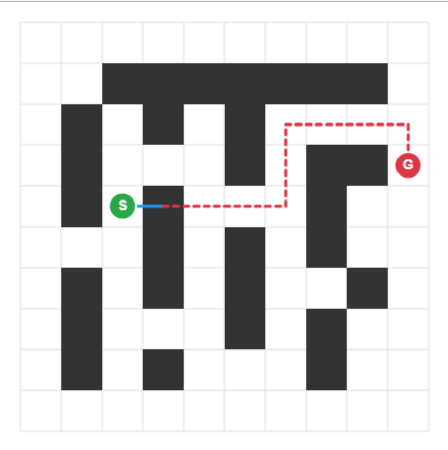
The image depicts a grid-based maze or pathfinding problem. A black-and-white grid represents obstacles (black squares) and traversable paths (white squares). A green circle labeled "S" marks the start position, and a red circle labeled "G" marks the goal. A dashed red line connects "S" to "G," indicating a calculated path through the grid.
### Components/Axes
- **Grid Structure**:
- 10x10 grid (approximate, based on visible cells).
- Black squares: Obstacles (non-traversable).
- White squares: Open paths (traversable).
- **Labels**:
- **S**: Green circle, positioned at grid coordinates (3, 4) (row 3, column 4, assuming top-left is (0,0)).
- **G**: Red circle, positioned at grid coordinates (8, 9) (row 8, column 9).
- **Path**:
- Dashed red line connects "S" to "G," forming a zigzag route around obstacles.
### Detailed Analysis
- **Start (S)**: Located in the left-middle section of the grid.
- **Goal (G)**: Positioned in the top-right corner.
- **Path Characteristics**:
- The dashed red line avoids black obstacles by navigating around them.
- The path includes 12 grid cells (including start and goal).
- Key turns occur at grid intersections (e.g., moving right, then down, then right again).
### Key Observations
1. The path is non-direct, requiring detours around obstacles.
2. The grid’s obstacle density suggests a moderately complex pathfinding challenge.
3. No alternative paths are marked, implying a single optimal solution.
### Interpretation
This diagram illustrates a pathfinding algorithm’s output, likely using methods like A* or Dijkstra’s, to navigate from "S" to "G" while avoiding obstacles. The dashed red line represents the shortest or most efficient route in terms of traversable cells. The absence of multiple paths suggests the algorithm prioritizes minimal distance or cost. The grid’s design could be used to test pathfinding logic, validate algorithm efficiency, or demonstrate spatial reasoning in computational systems.
**Note**: No numerical data, legends, or textual annotations beyond "S" and "G" are present. The grid’s dimensions and obstacle distribution are inferred visually.