TECHNICAL ASSET FINGERPRINT
8f6f10b5e65188ff58317ac3
Click to view fullscreen
Press ESC or click to close
FOUND IN PAPERS
EXPERT: healer-alpha-free VERSION 1
RUNTIME: free/openrouter/healer-alpha
INTEL_VERIFIED
\n
## Directed Graph Diagram: Object Property and Relationship Model
### Overview
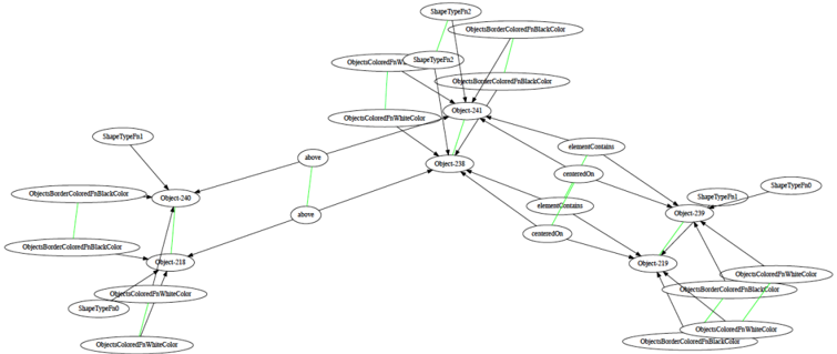
The image displays a directed graph (node-link diagram) representing a structured model of objects, their properties (shape types, colors), and spatial or containment relationships. The diagram consists of oval-shaped nodes containing text labels, connected by directed edges (arrows) with relationship labels. A subset of connections is highlighted with green lines, which appear to represent a distinct type of relationship, possibly property assignment or type definition, as they lack explicit text labels.
### Components/Axes
* **Node Types:** All nodes are oval-shaped. The text within defines an entity, which can be:
* **Object Instances:** Labeled as `Object` followed by a number (e.g., `Object240`, `Object238`, `Object249`).
* **Property Types:** Labeled as `ShapeTypeP` followed by a number (e.g., `ShapeTypeP1`, `ShapeTypeP2`).
* **Color Properties:** Labeled descriptively, such as `ObjectsBorderColorsBlackColor`, `ObjectsColoredWithWhiteColor`, `ObjectsColoredWithBlackColor`.
* **Edge Types:**
* **Black Directed Arrows:** Represent explicit, labeled relationships. The labels are:
* `above`
* `contains`
* `containsOn`
* **Green Lines:** Represent an unlabeled relationship, connecting property nodes to object nodes. Their consistent color suggests a semantic grouping distinct from the black arrows.
### Detailed Analysis
The graph can be segmented into several clusters based on connectivity and spatial grouping.
**1. Left Cluster (Centered around Object240 and Object238):**
* **Object240** is a central node.
* It is connected **from** `ShapeTypeP1` via a black arrow labeled `above`.
* It is connected **from** `ObjectsBorderColorsBlackColor` via a green line.
* It is connected **from** `ObjectsColoredWithWhiteColor` via a green line.
* It has a black arrow labeled `above` pointing **to** `Object238`.
* **Object238** is another central node.
* It receives the `above` arrow from `Object240`.
* It is connected **from** `ObjectsBorderColorsBlackColor` via a green line.
* It is connected **from** `ObjectsColoredWithWhiteColor` via a green line.
* It has a black arrow labeled `contains` pointing **to** `Object249`.
* It has a black arrow labeled `containsOn` pointing **to** `Object259`.
* **Peripheral Nodes in Left Cluster:**
* `ShapeTypeP1` (top-left) points to `Object240`.
* `ObjectsBorderColorsBlackColor` (far left) has green lines to both `Object240` and `Object238`.
* `ObjectsColoredWithWhiteColor` (bottom-left) has green lines to both `Object240` and `Object238`.
**2. Top Cluster (Centered around Object241):**
* **Object241** is a central node.
* It is connected **from** `ShapeTypeP2` via a green line.
* It is connected **from** `ObjectsBorderColorsBlackColor` via a green line.
* It is connected **from** `ObjectsColoredWithWhiteColor` via a green line.
* It has a black arrow labeled `contains` pointing **to** `Object238`.
* It has a black arrow labeled `containsOn` pointing **to** `Object249`.
* **Peripheral Nodes in Top Cluster:**
* `ShapeTypeP2` (top-center) has a green line to `Object241`.
* `ObjectsBorderColorsBlackColor` (top-right) has a green line to `Object241`.
* `ObjectsColoredWithWhiteColor` (top-right) has a green line to `Object241`.
**3. Right Cluster (Centered around Object249 and Object259):**
* **Object249** is a central node.
* It receives a `contains` arrow from `Object238`.
* It receives a `containsOn` arrow from `Object241`.
* It is connected **from** `ShapeTypeP1` via a green line.
* It is connected **from** `ObjectsColoredWithWhiteColor` via a green line.
* It has a black arrow labeled `contains` pointing **to** `Object259`.
* **Object259** is a central node.
* It receives a `containsOn` arrow from `Object238`.
* It receives a `contains` arrow from `Object249`.
* It is connected **from** `ShapeTypeP1` via a green line.
* It is connected **from** `ObjectsBorderColorsBlackColor` via a green line.
* It is connected **from** `ObjectsColoredWithWhiteColor` via a green line.
* **Peripheral Nodes in Right Cluster:**
* `ShapeTypeP1` (far right) has green lines to both `Object249` and `Object259`.
* `ObjectsColoredWithWhiteColor` (bottom-right) has green lines to both `Object249` and `Object259`.
* `ObjectsBorderColorsBlackColor` (bottom-right) has a green line to `Object259`.
### Key Observations
1. **Recurring Properties:** The properties `ObjectsBorderColorsBlackColor`, `ObjectsColoredWithWhiteColor`, and `ShapeTypeP1` are assigned (via green lines) to multiple objects across different clusters, indicating shared attributes.
2. **Relationship Hierarchy:** The labeled black arrows (`above`, `contains`, `containsOn`) define a clear spatial and compositional hierarchy. `Object240` is `above` `Object238`. `Object238` and `Object241` both `contain` or `containOn` other objects (`Object249`, `Object259`), suggesting a nested structure.
3. **Dual Connection Types:** The use of two distinct visual connectors (black labeled arrows vs. green unlabeled lines) strongly implies two different semantic relationships in the model, such as "spatial/compositional relation" vs. "property assignment."
4. **Graph Density:** The diagram is densely connected, with several objects (`Object238`, `Object249`, `Object259`) acting as hubs with multiple incoming and outgoing connections.
### Interpretation
This diagram models a **scene graph** or an **object-oriented property model**. It defines a set of objects (`ObjectXXX`) and specifies:
* **Their Intrinsic Properties:** Shape type (`ShapeTypeP1/P2`) and color attributes (border and fill colors) via the green-line relationships.
* **Their Spatial and Compositional Relationships:** How objects are positioned relative to each other (`above`) and how they are grouped or contained within one another (`contains`, `containsOn`).
The structure suggests a system for describing a visual layout or a UI component hierarchy. For example, `Object240` (perhaps a header) is `above` `Object238` (a main container), which in turn `contains` `Object249` and `Object259` (child elements like buttons or panels). The consistent assignment of `ShapeTypeP1` and white fill to many objects might indicate a default style, while the specific assignment of `ShapeTypeP2` to `Object241` marks it as a distinct element type. The model separates the *what* (properties) from the *where* (relationships), providing a formal blueprint for reconstructing or analyzing the described visual structure.
DECODING INTELLIGENCE...