\n
## Diagram: Dependency Graph
### Overview
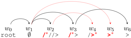
The image depicts a directed graph illustrating dependencies between six nodes labeled w0 through w6. The nodes are arranged horizontally, and arrows indicate the direction of dependency. Some arrows are solid black, while others are dashed red. Node labels include symbols and text.
### Components/Axes
The diagram consists of:
* **Nodes:** w0, w1, w2, w3, w4, w5, w6.
* **Labels:** Each node has a label below it: "root", "∅", "/*//>", "/*>", "/>", ">".
* **Arrows:** Solid black arrows represent one type of dependency, and dashed red arrows represent another.
* **Arrow Origins:** The arrows originate from the nodes on the left and point to nodes on the right.
### Detailed Analysis or Content Details
* **w0 (root):** Has a solid black arrow pointing to w1 and w2.
* **w1 (∅):** Has a solid black arrow pointing to w2, w3, w4, w5, and w6.
* **w2 (/*//>):** Has a solid black arrow pointing to w3, w4, w5, and w6.
* **w3 (/*>):** Has a solid black arrow pointing to w4, w5, and w6.
* **w4 (/>):** Has a solid black arrow pointing to w5 and w6.
* **w5 (>):** Has a solid black arrow pointing to w6.
* **w6 (>):** Has no outgoing arrows.
* **Red Dashed Arrows:** There is a red dashed arrow from w0 to w3, w0 to w4, w0 to w5, w0 to w6, w1 to w4, w1 to w5, w1 to w6, w2 to w5, w2 to w6, w3 to w6, w4 to w6, and w5 to w6.
### Key Observations
The diagram shows a hierarchical dependency structure. The "root" node (w0) is the most general, and dependencies become more specific as you move to the right. The red dashed arrows indicate additional dependencies that are not captured by the solid black arrows. The node labels appear to represent some form of pattern or code snippet.
### Interpretation
This diagram likely represents a parsing or compilation process, or a state machine. The nodes could represent states or grammar rules, and the arrows represent transitions or dependencies between them. The root node represents the starting point, and the nodes to the right represent increasingly specific states or rules. The red dashed arrows suggest alternative or conditional dependencies. The symbols in the node labels (/*, /, >, ∅) could be related to regular expressions or programming language syntax. The diagram illustrates a directed acyclic graph (DAG), meaning there are no cycles in the dependencies. This is important for ensuring that the process can be completed in a well-defined order. The diagram suggests a process where each element builds upon the previous, with the root element being the foundation. The red arrows indicate that there are multiple paths to reach certain states, adding complexity to the process.