# Technical Diagram Analysis
## Overview
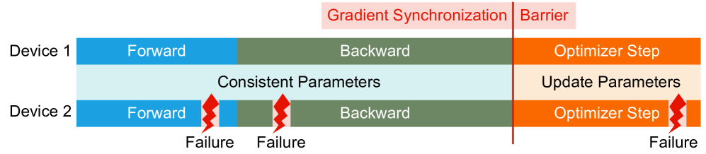
The diagram illustrates a distributed computing workflow across two devices (Device 1 and Device 2) with synchronized parameter updates and failure points. The workflow is divided into three primary phases: **Forward**, **Backward**, and **Optimizer Step**, separated by a **Gradient Synchronization Barrier**.
---
## Key Components
### 1. **Device 1**
- **Forward Phase** (Blue):
- Text: "Forward"
- Color: Blue
- Spatial Position: Leftmost segment of Device 1
- **Backward Phase** (Green):
- Text: "Backward"
- Color: Green
- Spatial Position: Middle segment of Device 1
- **Optimizer Step** (Orange):
- Text: "Optimizer Step"
- Color: Orange
- Spatial Position: Rightmost segment of Device 1
### 2. **Device 2**
- **Forward Phase** (Blue):
- Text: "Forward"
- Color: Blue
- Spatial Position: Leftmost segment of Device 2
- **Failure Indicator**: Red lightning bolt labeled "Failure" (appears at the end of the Forward phase)
- **Backward Phase** (Green):
- Text: "Backward"
- Color: Green
- Spatial Position: Middle segment of Device 2
- **Failure Indicator**: Red lightning bolt labeled "Failure" (appears at the end of the Backward phase)
- **Optimizer Step** (Orange):
- Text: "Optimizer Step"
- Color: Orange
- Spatial Position: Rightmost segment of Device 2
- **Failure Indicator**: Red lightning bolt labeled "Failure" (appears at the end of the Optimizer Step)
### 3. **Gradient Synchronization Barrier**
- **Label**: "Gradient Synchronization"
- Color: Red
- Spatial Position: Vertical red line between Device 1 and Device 2
- Context: Acts as a synchronization checkpoint between devices
### 4. **Consistent Parameters**
- **Label**: "Consistent Parameters"
- Color: Light Blue
- Spatial Position: Overlaps the Forward and Backward phases of both devices
- Function: Indicates parameters maintained across devices during synchronization
### 5. **Parameter Update**
- **Label**: "Update Parameters"
- Color: Light Orange (shaded area)
- Spatial Position: Overlaps the Optimizer Step of Device 1
- Function: Indicates parameter updates occur after synchronization
---
## Failure Points
- **Device 2 Failures**:
1. **Forward Phase Failure**: Red lightning bolt at the end of Device 2's Forward phase.
2. **Backward Phase Failure**: Red lightning bolt at the end of Device 2's Backward phase.
3. **Optimizer Step Failure**: Red lightning bolt at the end of Device 2's Optimizer Step.
---
## Workflow Flow
1. **Device 1**:
- Executes Forward → Backward → Optimizer Step.
- Parameters remain consistent during Forward and Backward phases.
- Updates parameters after synchronization.
2. **Device 2**:
- Executes Forward → Backward → Optimizer Step.
- Experiences failures at all three stages (Forward, Backward, Optimizer Step).
3. **Synchronization**:
- The **Gradient Synchronization Barrier** ensures parameter consistency between devices before proceeding to the Optimizer Step.
---
## Color Legend
| Color | Component/Label |
|-------------|-------------------------------|
| Blue | Forward Phase |
| Green | Backward Phase |
| Orange | Optimizer Step |
| Light Blue | Consistent Parameters |
| Light Orange| Parameter Update |
| Red | Gradient Synchronization Barrier |
| Red Lightning Bolt | Failure Indicator |
---
## Notes
- No numerical data or chart trends are present; the diagram focuses on workflow structure and failure points.
- All textual labels and color codings are explicitly mapped for clarity.
- Failures in Device 2 are distributed across all three phases, suggesting systemic instability.