## Diagram: Network Flow
### Overview
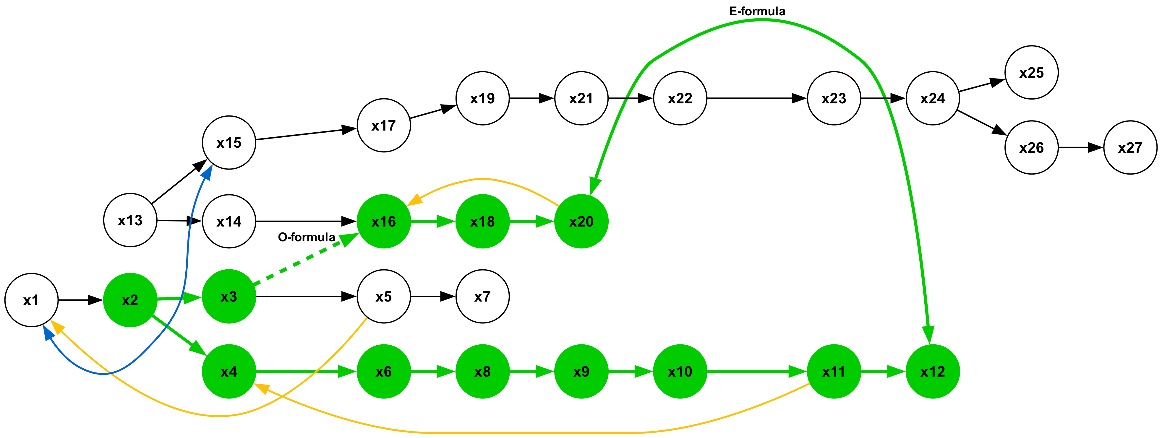
The image is a network diagram illustrating a flow or process. It consists of nodes (circles) labeled with "x" followed by a number, and directed edges (arrows) indicating the direction of flow. Some nodes are colored green, while others are white. There are also colored arcs indicating specific formulas.
### Components/Axes
* **Nodes:** Represented by circles, labeled from x1 to x27.
* **Edges:** Represented by arrows, indicating the direction of flow between nodes.
* **Node Colors:** Green nodes likely represent a specific state or condition. White nodes likely represent a different state or condition.
* **Arcs:** Curved lines representing specific formulas.
* **Green Arc:** Labeled "E-formula"
* **Dashed Green Arc:** Labeled "O-formula"
* **Blue Arc:** Connects x4 to x1
* **Yellow Arcs:** Connect x16 to x4, x18 to x6, x20 to x11
### Detailed Analysis or ### Content Details
* **Node x1:** Located at the bottom-left.
* **Node x2:** Located to the right of x1, colored green.
* **Node x3:** Located to the right of x2, colored green.
* **Node x4:** Located below x3, colored green.
* **Node x5:** Located to the right of x3, colored white.
* **Node x6:** Located below x5, colored green.
* **Node x7:** Located to the right of x5, colored white.
* **Node x8:** Located to the right of x6, colored green.
* **Node x9:** Located to the right of x8, colored green.
* **Node x10:** Located to the right of x9, colored green.
* **Node x11:** Located to the right of x10, colored green.
* **Node x12:** Located to the right of x11, colored green.
* **Node x13:** Located above and to the left of x2, colored white.
* **Node x14:** Located to the right of x13, colored white.
* **Node x15:** Located above x13, colored white.
* **Node x16:** Located above x6, colored green.
* **Node x17:** Located above x5, colored white.
* **Node x18:** Located to the right of x16, colored green.
* **Node x19:** Located above x17, colored white.
* **Node x20:** Located to the right of x18, colored green.
* **Node x21:** Located to the right of x19, colored white.
* **Node x22:** Located to the right of x21, colored white.
* **Node x23:** Located to the right of x22, colored white.
* **Node x24:** Located to the right of x23, colored white.
* **Node x25:** Located above and to the right of x24, colored white.
* **Node x26:** Located below and to the right of x24, colored white.
* **Node x27:** Located to the right of x26, colored white.
**Flow Paths:**
* x1 -> x2
* x2 -> x3
* x2 -> x4
* x3 -> x5
* x3 -> x16 (O-formula, dashed green line)
* x4 -> x6
* x5 -> x7
* x6 -> x8
* x8 -> x9
* x9 -> x10
* x10 -> x11
* x11 -> x12
* x13 -> x15
* x14 -> x15
* x16 -> x18
* x17 -> x19
* x18 -> x20
* x19 -> x21
* x21 -> x22
* x22 -> x23
* x23 -> x24
* x24 -> x25
* x24 -> x26
* x26 -> x27
**Arcs:**
* **E-formula (Green):** Arcs from x21, x22, x23, and x24 back to x12.
* **O-formula (Dashed Green):** Arcs from x3 to x16.
* **Blue:** Arcs from x4 to x1.
* **Yellow:** Arcs from x16 to x4, x18 to x6, and x20 to x11.
### Key Observations
* The diagram shows a complex network with multiple paths and feedback loops.
* The green nodes (x2, x3, x4, x6, x8, x9, x10, x11, x12, x16, x18, x20) seem to represent a primary flow path, while the white nodes (x1, x5, x7, x13, x14, x15, x17, x19, x21, x22, x23, x24, x25, x26, x27) may represent secondary paths or decision points.
* The E-formula creates a significant feedback loop from the later stages (x21-x24) back to x12.
* The O-formula connects x3 to x16.
* The blue and yellow arcs create additional feedback loops.
### Interpretation
The diagram likely represents a process flow, algorithm, or system with multiple interconnected components. The green nodes could represent active or "on" states, while the white nodes could represent inactive or "off" states. The formulas (E-formula and O-formula) likely represent specific calculations or transformations applied to the data as it flows through the network. The feedback loops suggest iterative processes or control mechanisms. The diagram could be used to model a variety of systems, such as a manufacturing process, a computer program, or a biological pathway.