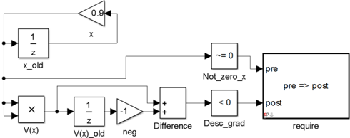
## Block Diagram: Simulink Model for Conditional Requirement Check
### Overview
The image displays a Simulink block diagram representing a logical and mathematical model that checks two conditions before asserting a requirement. The diagram processes two input signals, `x` and `V(x)`, through a series of operations (delays, gains, comparisons) and feeds the results into a final "require" block. The overall flow is from left to right, with a feedback loop in the upper section.
### Components/Axes
The diagram consists of interconnected blocks, each with a specific function and label. The primary components are:
1. **Input Signals (Left Side):**
* `x`: An input signal entering the system.
* `V(x)`: A second input signal, likely representing a function of `x`.
2. **Processing Blocks (Upper Path - for `x`):**
* **Unit Delay (`x_old`):** A block labeled `x_old` with `1/z` inside, indicating it delays the `x` signal by one time step.
* **Gain (0.9):** A triangular gain block with the value `0.9`. It takes the output of `x_old` and feeds it back to the input of the `x_old` block, creating a recursive loop. The output of this gain is also labeled `x`.
* **Relational Operator (`Not_zero_x`):** A block labeled `Not_zero_x` with the symbol `~=0` (not equal to zero). It receives the current `x` signal and checks if it is non-zero.
3. **Processing Blocks (Lower Path - for `V(x)`):**
* **Product/Function Block (`V(x)`):** A block labeled `V(x)` with an `X` symbol inside. It processes the `V(x)` input.
* **Unit Delay (`V(x)_old`):** A block labeled `V(x)_old` with `1/z` inside, delaying the processed `V(x)` signal.
* **Gain (`neg`):** A triangular gain block labeled `neg` with a value of `-1`. It inverts the signal from `V(x)_old`.
* **Sum Block (`Difference`):** A block labeled `Difference` with two `+` signs. It adds the output from `V(x)_old` and the inverted signal from `neg`, effectively computing `V(x)_old - V(x)_old_processed` (the exact operation depends on the `V(x)` block's function).
* **Relational Operator (`Desc_grad`):** A block labeled `Desc_grad` with the symbol `<0` (less than zero). It checks if the output of the `Difference` block is negative.
4. **Output/Assertion Block (Right Side):**
* **Requirement Block (`require`):** A large rectangular block labeled `require`. Inside, it contains the logical statement `pre => post` (if pre-condition, then post-condition).
* **Input `pre`:** Receives the output from the `Not_zero_x` block.
* **Input `post`:** Receives the output from the `Desc_grad` block.
* This block asserts that if the pre-condition (`x` is not zero) is true, then the post-condition (the difference is negative) must also be true.
### Detailed Analysis
* **Signal Flow & Logic:**
1. The `x` signal is delayed (`x_old`) and fed back through a `0.9` gain, creating a damped recursive relationship: `x_new = 0.9 * x_old`.
2. The current `x` is checked for being non-zero (`Not_zero_x`).
3. The `V(x)` signal is processed, delayed (`V(x)_old`), and used to compute a difference with its own inverted value (`Difference` block).
4. This difference is checked to see if it is negative (`Desc_grad`), which could indicate a descending gradient or a decrease in value.
5. The two Boolean results (from `Not_zero_x` and `Desc_grad`) are fed as the `pre` and `post` conditions into the `require` block.
* **Spatial Grounding:**
* The **upper processing path** for `x` is located in the top-left to top-center region.
* The **lower processing path** for `V(x)` is located in the bottom-left to bottom-center region.
* The **`require` assertion block** is positioned prominently on the right side, acting as the convergence point for both logical paths.
* The **feedback loop** (gain `0.9`) is located at the very top, connecting the output of `x_old` back to its input.
### Key Observations
1. **Conditional Assertion:** The core function is not to compute a value but to enforce a logical rule (`pre => post`). The system will likely flag an error or halt if `x` is not zero but the computed difference is not negative.
2. **Recursive Element:** The `0.9` gain feedback loop on `x_old` suggests the model is concerned with the behavior of `x` over time, possibly in a discrete-time simulation.
3. **Potential Optimization Context:** The labels `V(x)` (often a cost function), `Desc_grad` (descending gradient), and the requirement for a negative difference strongly suggest this diagram models a condition for a valid descent step in an optimization algorithm (e.g., ensuring the gradient is negative when the parameter is non-zero).
### Interpretation
This Simulink model implements a **safety or validity check** for a dynamic system, most likely within an optimization or control algorithm context. It formalizes the rule: **"If the variable `x` is active (non-zero), then the change in its associated function `V(x)` must be negative (indicating descent)."**
The diagram translates a mathematical or algorithmic precondition into a executable, visual model. The `require` block acts as an automated assertion that would trigger during simulation if the condition is violated, helping to debug the algorithm or ensure it operates within defined theoretical bounds. The presence of unit delays (`1/z`) indicates this check is performed at each discrete time step of a simulation. The model's structure isolates the two conditions (`x ≠ 0` and `ΔV < 0`) before combining them logically, making the system's intent clear and modular.