## Simulink Diagram: Discrete System with Feedback and Conditionals
### Overview
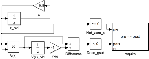
The image depicts a Simulink diagram representing a discrete system. It involves feedback loops, multiplication, delay blocks (1/z), difference calculation, and conditional checks. The system appears to be designed to enforce a requirement based on certain conditions.
### Components/Axes
* **Blocks:**
* **Gain Block (0.9):** A triangular block labeled "0.9".
* **Delay Block (1/z):** Two rectangular blocks labeled "1/z".
* **Multiplication Block:** A rectangular block labeled "x".
* **Gain Block (-1):** A triangular block labeled "-1".
* **Sum Block:** A square block with "++" inside, labeled "Difference".
* **Relational Operator Block (~= 0):** A rectangular block labeled "~= 0".
* **Relational Operator Block (< 0):** A rectangular block labeled "< 0".
* **Assertion Block:** A rectangular block labeled "require".
* **Labels:**
* "x" (associated with the 0.9 gain block)
* "x_old" (associated with the first 1/z block)
* "V(x)" (associated with the multiplication block)
* "V(x)_old" (associated with the second 1/z block)
* "neg" (associated with the -1 gain block)
* "Not_zero_x" (associated with the ~= 0 block)
* "Desc_grad" (associated with the < 0 block)
* "pre" (input to the "require" block)
* "post" (input to the "require" block)
* "pre => post" (inside the "require" block)
### Detailed Analysis
1. **Top Feedback Loop:**
* The signal "x" is multiplied by a gain of 0.9.
* The output is fed back into a delay block (1/z), producing "x_old".
* "x_old" is fed back to the input of the system.
2. **Bottom Branch:**
* The signal "x" and "x_old" are multiplied, resulting in "V(x)".
* "V(x)" is passed through a delay block (1/z), resulting in "V(x)_old".
* "V(x)_old" is multiplied by -1, resulting in "neg".
* "neg" is added to "V(x)", resulting in "Difference".
3. **Conditional Checks and Assertion:**
* "x" is checked to see if it is not equal to 0 (~= 0), resulting in "Not_zero_x".
* "Difference" is checked to see if it is less than 0 (< 0), resulting in "Desc_grad".
* "Not_zero_x" is connected to the "pre" input of the "require" block.
* "Desc_grad" is connected to the "post" input of the "require" block.
* The "require" block asserts that "pre => post" must be true.
### Key Observations
* The system involves two feedback loops.
* The "require" block enforces a condition based on the outputs of the relational operator blocks.
* The delay blocks (1/z) indicate that this is a discrete-time system.
### Interpretation
The Simulink diagram represents a discrete system with feedback and conditional logic. The system calculates "V(x)" based on the current and previous values of "x". It then checks if "x" is not zero and if the "Difference" is less than zero. The "require" block asserts that if "x" is not zero ("pre" is true), then the "Difference" must be less than zero ("post" is true). This suggests that the system is designed to ensure that a certain condition (related to the gradient or difference) is met when "x" is non-zero. The system likely implements a form of control or optimization algorithm where the condition "pre => post" must always hold.