\n
## Diagram: Control System Flowchart
### Overview
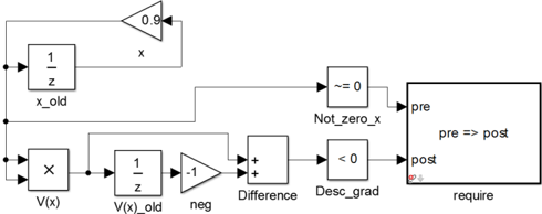
The image depicts a control system flowchart, likely implemented in a software like Simulink. It illustrates a feedback loop with several processing blocks and conditional statements. The flowchart appears to be designed to regulate a variable 'x' based on its previous value and a function 'V(x)'.
### Components/Axes
The diagram consists of the following components:
* **Input:** V(x)
* **Delay Blocks:** "1/z" labeled as "x\_old" and "V(x)\_old"
* **Gain Blocks:** 0.9 and -1
* **Summing Junction:** "+" labeled as "Difference"
* **Comparison Blocks:** "~= 0" labeled as "Not\_zero\_x" and "< 0" labeled as "Desc\_grad"
* **Conditional Block:** A rectangular block labeled "require" with internal text "pre => post" and outputs "pre" and "post".
There are no explicit axes in this diagram, as it represents a flow of data and control rather than a graphical representation of numerical data.
### Detailed Analysis or Content Details
The flowchart can be described as follows:
1. **Input:** The system receives an input signal V(x).
2. **Delay:** V(x) is delayed by one time step using a "1/z" block, storing the previous value as V(x)\_old.
3. **Negation:** V(x)\_old is multiplied by -1.
4. **Difference Calculation:** The negated V(x)\_old is added to V(x) at the summing junction, resulting in "Difference".
5. **Descending Gradient Check:** The "Difference" is checked to see if it is less than 0 using the "< 0" block, labeled "Desc\_grad".
6. **Non-Zero Check:** The current value of 'x' is checked to see if it is not equal to 0 using the "~= 0" block, labeled "Not\_zero\_x".
7. **Conditional Execution:** The outputs of "Not\_zero\_x" and "Desc\_grad" feed into the "require" block. The internal text "pre => post" suggests that if the "pre" condition (Not\_zero\_x) is met, then the "post" condition (Desc\_grad) is evaluated. The block outputs "pre" and "post".
8. **Feedback Loop:** The current value of 'x' is multiplied by 0.9 and fed back into the system, along with the input V(x). The previous value of 'x' is stored in the "x\_old" block.
### Key Observations
* The system incorporates a feedback loop, suggesting it's designed for iterative refinement or control.
* The conditional block "require" acts as a gate, controlling the flow of execution based on the conditions "Not\_zero\_x" and "Desc\_grad".
* The use of delay blocks ("1/z") indicates that the system considers the history of the input and the variable 'x'.
* The negation of V(x)\_old suggests a comparison or subtraction operation is being performed.
### Interpretation
This diagram likely represents an optimization or control algorithm. The system appears to be attempting to adjust 'x' based on the input V(x) and its previous value. The "Desc\_grad" check suggests the algorithm is looking for a descending gradient, which is common in optimization problems. The "require" block enforces conditions before proceeding, potentially ensuring stability or preventing division by zero. The feedback loop with the gain of 0.9 suggests a damping effect, preventing oscillations.
The flowchart is a visual representation of a mathematical or logical process. It doesn't provide specific numerical data, but rather illustrates the relationships between different components and the flow of control. The diagram is a high-level abstraction, and the specific implementation details would depend on the context in which it is used. The "pre => post" notation within the "require" block is a logical implication, meaning that the "post" output is only valid if the "pre" condition is true. This suggests a dependency between the two conditions.